
Designing movable subassemblies in the sketch skeleton
Quickly dimensioning subassemblies that are movable in themselves
Links on the topic: The Video about cylinder design in the sketch skeleton at Youtube or DailyMotion and the short presentation (sorry, only in German) as PDF.
Efficiently designing cylinders and similar movable parts
When movable components are provided in an assembly, their parameters often change during the design process. If prefabricated models, e.g. imported models from the manufacturer, are used from the beginning, any change in dimensioning means some effort. In addition, it is easy to make mistakes if the design changes but the imported model has not yet been replaced. For custom-made parts, of course, the suppliers' models are only available long after the design phase, and for inquiries, a request drawing of the affected parts often has to be created.
If components to be imported are only installed at the end of the design phase, the risk of errors increases because space conflicts or design errors can easily be overlooked.
Skeleton modeling offers a simple solution here, as we have already seen in the design phase functional and meaningful models of catalog parts in assemblies without having additional modification effort in case of geometry changes.
To do this, we place a skeleton-controlled replacement model in the assembly, that contains all features essential for the design and is completely controlled by the skeleton. Only when the geometry is finally fixed do we install the import models from the suppliers. This tutorial shows how to proceed using a simple cylinder as an example.
Movement specifications of the environment
Before the cylinder itself can be designed, the requirements must be sketched. Intended attachment points in the surrounding parts must be designed. For movable connections, the elements relevant for the design must be drawn in all important positions, i.e. at least in both end positions. In these environment sketches, dimensions can already be entered, possibly as reference dimensions, which are used as input quantities for the rough calculation.
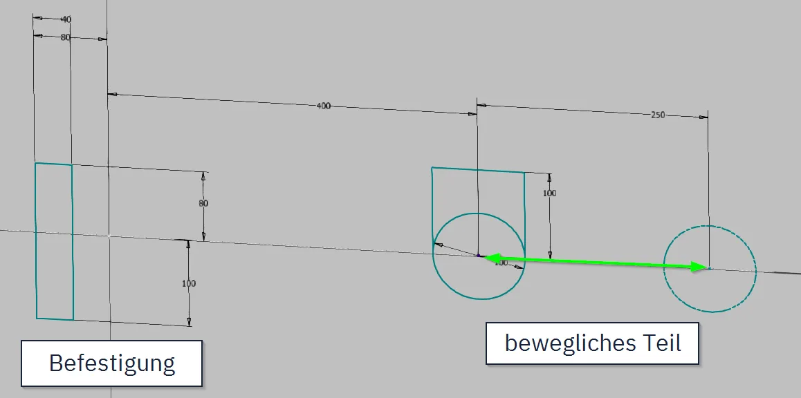
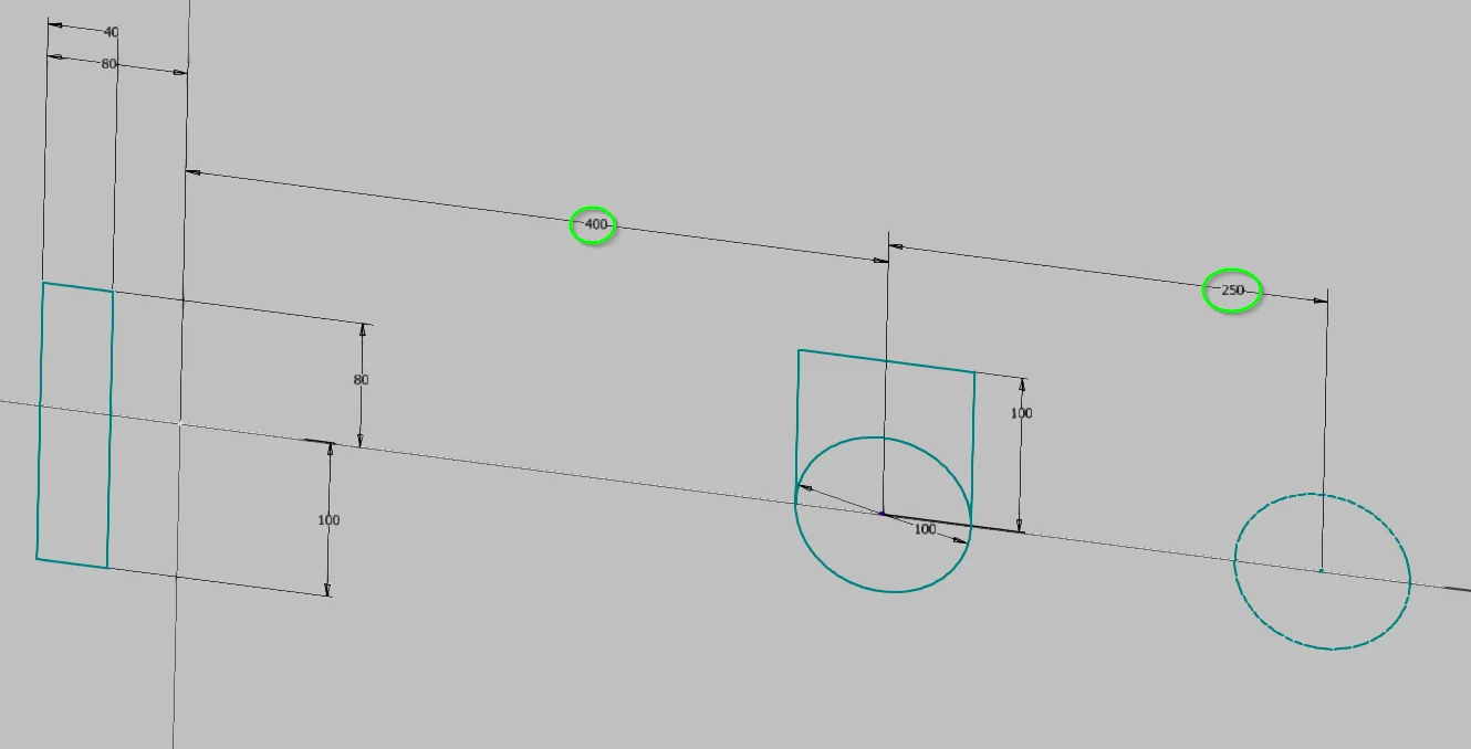
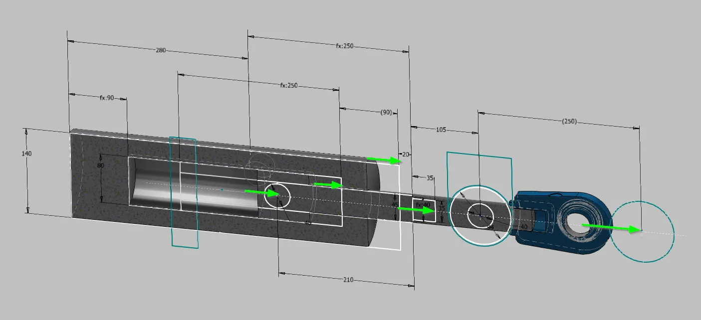
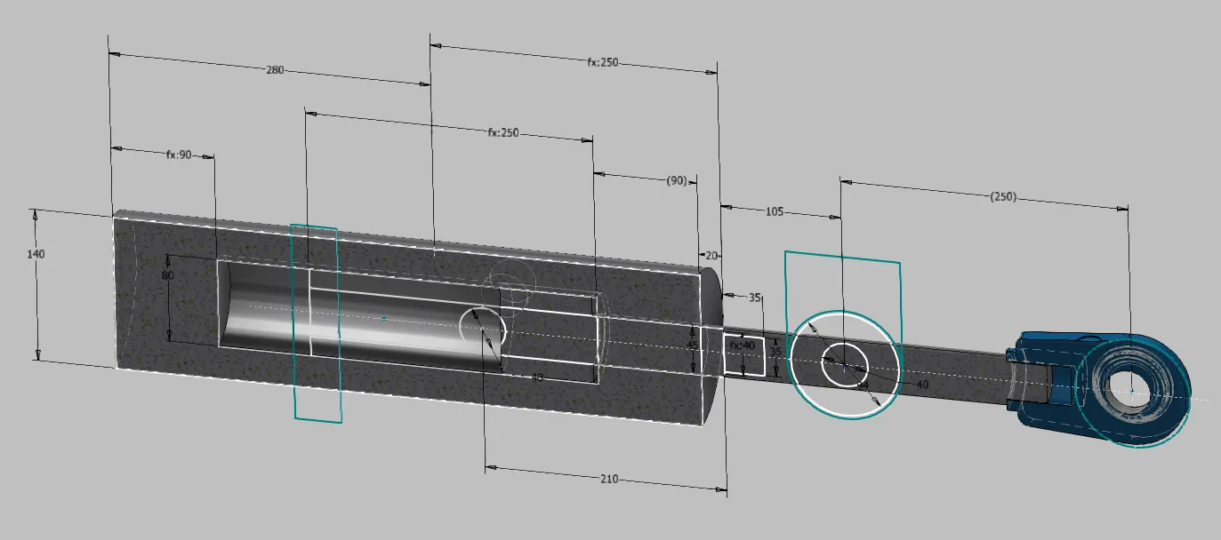
In the example, the cylinder is to be attached to a surface with bearing blocks and a pivot pin and coupled to its load with a clevis. Lugs are provided on the load side for this purpose. Figure 1.1 shows this starting position. In a real design, of course, many more components of the environment would be drawn; I have omitted that in this example for clarity. In addition, I drew the design directly in the cylinder assembly; it would normally be in the skeleton of the parent assembly and would be selectively derived into the cylinder assembly.
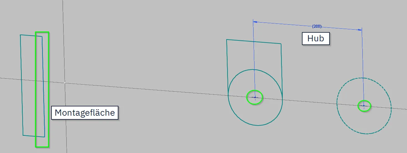
A new sketch is created for the cylinder. The elements of the environment relevant for the cylinder design are projected. In this case, these are only the centers of the clevis in the end positions. If the position of the pivot pin is to be fixed according to the mounting surface, this is also required. The stroke is inserted as a reference dimension, as can be seen in Figure 1.2. It is advisable to name the parameter. If reserve stroke is planned, corresponding points are drawn offset from the reference points and all dimensions related to the stroke are applied to these instead of to the reference points.
Mapping design data of the cylinder
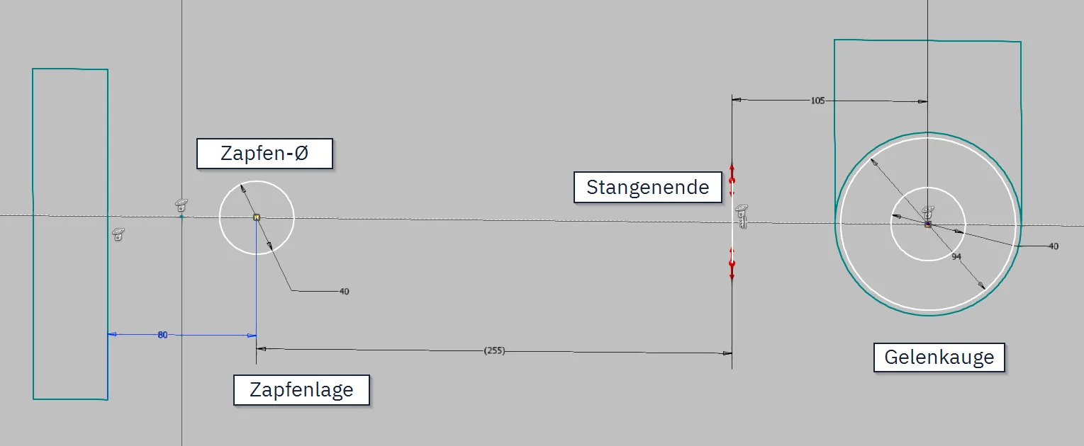
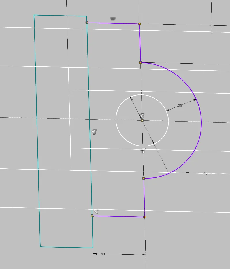
Next, the interfaces of the cylinder are drawn. Here we limit ourselves to the elements relevant for function and space planning. From the clevis, we need the pin diameter (small circle), the distance from pin center to formal rod end (vertical line), and the outer diameter of the clevis, as shown in Figure 1.3. In addition, the attachment of the cylinder housing, in this case a pivot pin in the side view as a circle, is drawn. The dimension to the mounting surface is the controlling dimension. The dimension to the rod end should be created as a reference dimension in order to check compliance with the permissible range according to catalog.
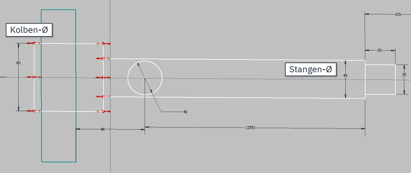
The piston is drawn as far as the length and sealing system are not known, simply with length = diameter (Figure 1.4); otherwise, space requirements for seals can of course also be drawn here. Piston diameter and rod diameter are known from the calculation or the catalog; the rod and the usually existing rod thread can be connected to the already drawn rod end line, which receives its previously undefined length through the coincident conditions at the end. Rod and piston are restricted symmetrically to the center line, so that only the length of the piston rod is still free.
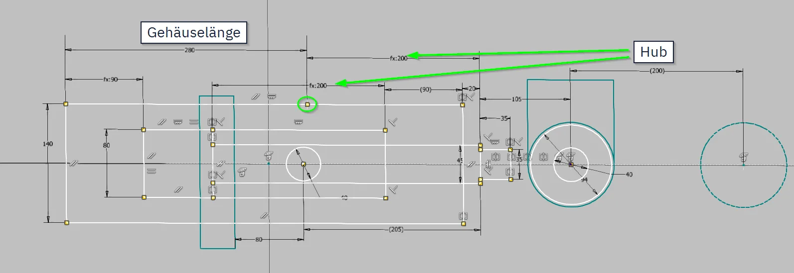
With the housing, the amount of work involved in changes is decided: The dependence of the total length on housing length and stroke must be mapped. For this purpose, I use a point at which both the catalog dimension for the housing length (often referred to as L0) and the stroke taken over from the input references via reference dimension are applied. This way, the housing always adapts to the stroke of the input references. The dimension for the total length is usually defined from the end of the housing to the end of the rod exclusive thread. In this example, I have greatly simplified the housing as a rectangle with the outer dimensions according to catalog, because usually only the largest outer dimensions are relevant for the design. If the actual contour of bottom, head, tube and intermediate flange is relevant, you can of course also include them.
The interior of the housing then consists in this simplified consideration only of the working space that is necessary from the piston surface to allow for the stroke. Here, too, the stroke dimension is transferred. If the exact structure of head and bottom is not known, the dimensions are simply equated, which makes the cylinder sketch completely defined.
In this example, a second view for the widths of the components is omitted; in a production model, you would naturally also draw them in the skeleton and not in the component.
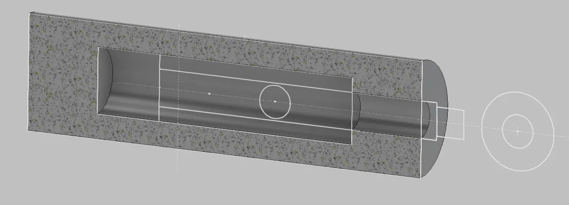
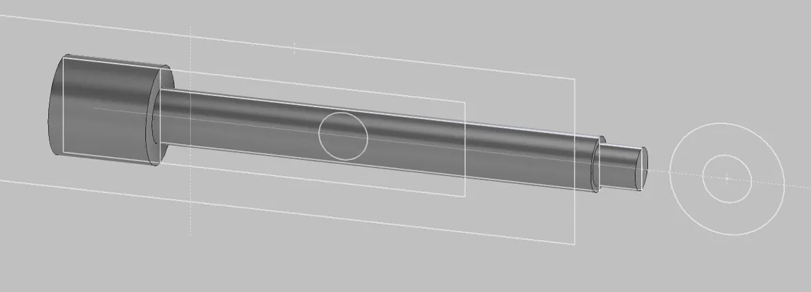
The individual parts for piston and housing are derived as usual (Figures 1.6 and 1.7).
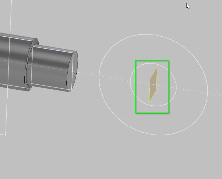
If the piston and housing are to be replaced by imported models later, it is advisable to place planes ("stroke start" and "stroke end") in the skeleton at both ends of the stroke according to Figure 1.8 in order to build the motion references on them later. This avoids direct references to the replacement model. In the piston part, a plane is created on the attachment point (e.g. center of clevis) as shown in Figure 1.9.

Assembly
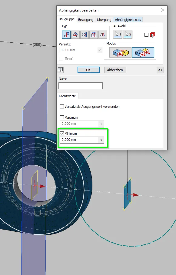
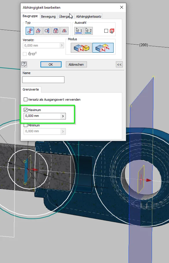
In the assembly, the housing is fixed or installed with corresponding movable conditions depending on the installation type. The piston is installed with its center axis on the center axis of the housing and the rotation is restricted with installation conditions on main planes. To represent the real stroke, planar dependencies with minimum or maximum distance (depending on the normal directions of the planes) 0 are used from both ends of the stroke. When installing with stroke end planes, it looks like in Figures 1.10 and 1.11; an assembly work plane can be used to decouple the stroke end conditions from the replacement part, which is installed on this plane. The piston is then movable exactly in the area of the defined stroke. The exact placement can then either be done via flexible installation and the parent assembly or by another condition that sets the specific stroke value. If necessary, intended rod ends such as clevises can be installed on the piston rod as needed, for example. In this example, I simply take an imported one, but if the size is still variable, a replacement model is also suitable here.
The hinge bracketsn can be drawn as a new sketch in the skeleton between the environment and the pivot pin, as shown in Figure 1.12.
If the input values change, the lengths of the piston rod, housing and movement area always follow consistently, as can be seen in Figures 1.13 to 1.15. Figure 1.14 shows the non-updated assembly with the already changed skeleton to illustrate the scope of the changes.
Conclusion
I hope that the principle has become clear from this highly simplified and out-of-context example. It can be transferred to many other movable parts where a similar dependence on input geometry exists. This method allows motion sequences to be clearly and reliably shown, planned and controlled with very little effort from the beginning of the design to the end of detailing.
If you need more in-depth advice on CAD methods, please click on Contact.
You are also welcome to download the short presentation (sorry, only in German) on the topic. It may be used freely in unchanged form, including commercially, provided the source is acknowledged (license: CC BY-ND).
You can also download the model files in the finished state of this tutorial.
Click the links to copy to clipboard
This page: https://r-kon.eu/cad-zylinder-im-skelett-auslegen.php
The video: https://youtu.be/QUudKPZZFMw (Youtube) / https://dai.ly/k2N9pFZX3svmw8D3als (DailyMotion)