
Indirectly controlled dimensions
Achieve manufacturing-compliant values and maintain size gradations in dimensions that can only be indirectly controlled
Links on the topic: The Video on indirectly controlled dimensions at Youtube or DailyMotion and the short presentation (sorry, only in German) as PDF.
When manufacturing dimensions and functional dimensions exclude each other and how they can still be compatible
There can only be one: This case often occurs when dimensioning sketches. I have always emphasized that functional dimensions must be used in top-down modeling. But what if manufacturing dimensions, which can only be set as reference dimensions and follow the functional dimensions, have to be rounded to a certain point or adjusted to a gradation?
To resolve this conflict, I usually use one of the following three solutions:
- "Switching dimensions": The functional dimension and the manufacturing dimension are placed in the sketch. If the functional dimension is changed, it is temporarily switched to the reference dimension and the manufacturing dimension to the controlling dimension. The manufacturing dimension is set to the nearest step value, switched back to the reference dimension, and the functional dimension is switched back to the controlling dimension.
- Offset dimensions: The functional conditions and dimensions are not placed directly on the contour to be controlled, but on a construction sketch element representing it. An additional controlling dimension is set as an offset dimension from the construction element to the "real" contour. The manufacturing dimension is then set as a reference dimension on the target contour as usual. The offset dimension is then adjusted so that the manufacturing dimension reaches the desired gradation. The offset dimension can also be automated with a formula. For this purpose, a helper dimension is placed with the alignment of the manufacturing dimension on the construction sketch element. In the simplest case, for linear dimensions, the formula for the offset would be: Offset = Round(helper dimension) - helper dimension, where instead of rounding to whole numbers, of course, rounding to 10s or 100s could also be done or Ceil or Floor could be used instead of Round. For standard gradations, iLogic is recommended.
-
Desired dimensions: In the simplest case, a desired dimension is set at a construction point or a construction line, and from this desired dimension, with iLogic or through rounding functions, the controlling value of the component contour is set.
In more complex relationships, a copy of the relevant contour is drawn as construction lines. This copy retroactively represents the functional relationships by first setting all conditions as with the original contour and all non-variable elements equal to it. Then, the dimension that may be changed to straighten out the manufacturing dimension is set as a reference dimension, and the manufacturing dimension is set as a controlling dimension. From the functional dimensioning of the original contour, a "curved" manufacturing dimension results. The straightened value for the manufacturing dimension is entered into the construction line copy (possibly again via formula), after which the target value of the controlling dimension can be read off at the corresponding reference dimension of the copy. Unfortunately, at this point, it can no longer be simply set equal because this would result in a circular reference. However, with iLogic, this could also be automated by first determining the target value based on the desired value and then setting the desired value to the target value.
Switching dimensions and offset dimensions
As an example of the switching and offset dimensions, the joint of a joint arm shown in Figure 1.1 is used. The segments connected at the joint must be bent to an angle specified by the environment. For this purpose, the plates must be given a corresponding clearance by welding them at an angle. The center and diameter of the joint and the orientation and width of the segments are predetermined by previous designs. Figure 1.2 shows the associated skeleton sketch with which the angled plates, represented by lines with degrees of freedom, are to be positioned collision-free. Since the arm geometry and thus the angle can change both during the design phase and in later modification constructions, it must be ensured that the construction remains collision-free even with angle changes.
The continuous line for both arm segments represents the side surface of the respective segment, while the adjacent shorter line from the centerline to the side of the respective other segment is the angled end face. Both arm segments are symmetrical, so only half of the collision-prone part is drawn. In order to dimension it in a manufacturing-compliant manner, the intersection point of the angled end faces, i.e., the endpoint of the short lines on their respective centerlines, should have a straight dimension from the center of the joint. In addition, the angle of the angled end face to the segment centerline should be straight.
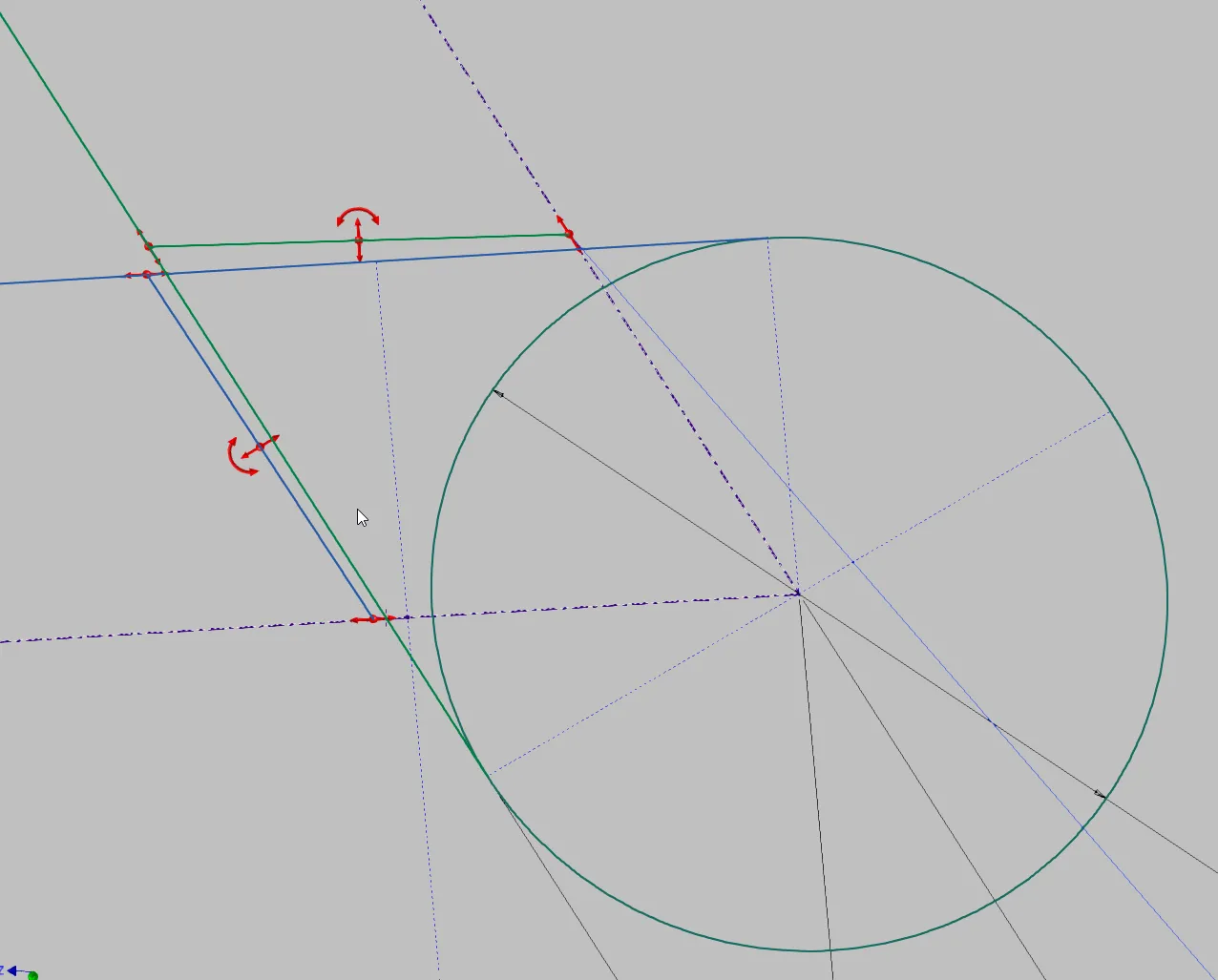
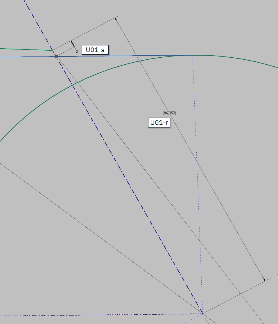
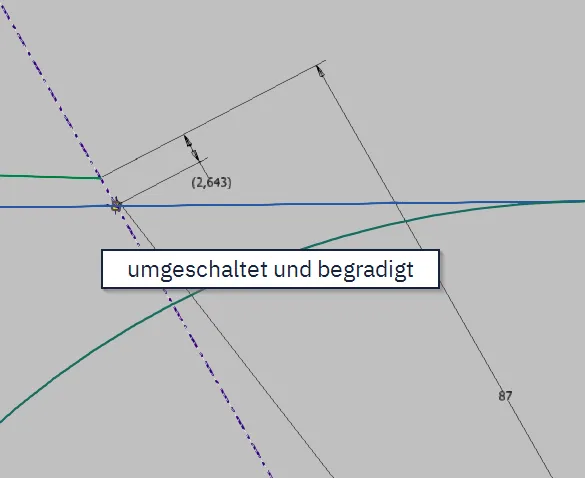
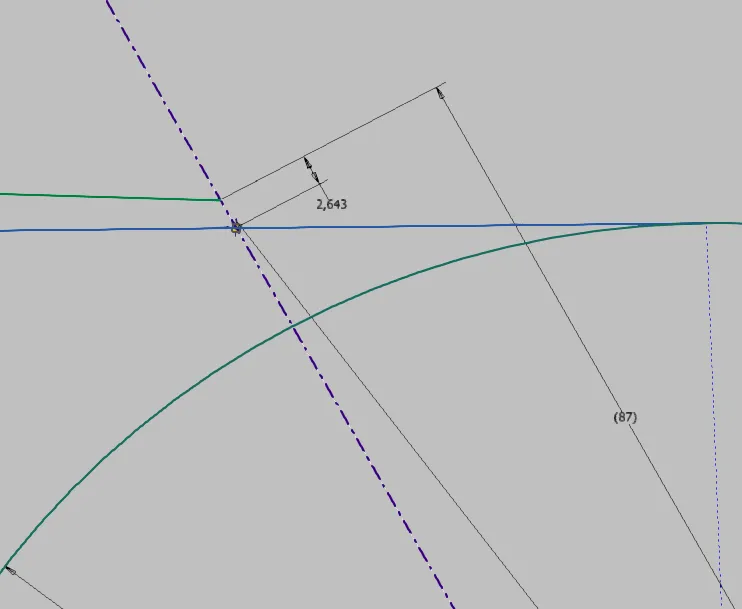
In the upper collision possibility shown in the image, I demonstrate the solution with switching dimensions. To avoid a collision, the green segment should be released. For this purpose, it is first necessary that the apex of the slope (green in image 1.3a) has a distance from the collision contour of the other segment (blue) that is dimensioned as controlling with a safe distance of 2 mm. This is the functional dimension. The distance from the center of the joint is the manufacturing-compliant dimension and is entered as a reference dimension. As expected, it results in a curved number. If, as shown in image 1.3b, the functional dimension is temporarily switched to the reference dimension and the manufacturing-compliant dimension to the controlling dimension, the manufacturing dimension can be straightened manually. However, this must be done manually after each change. After that, the manufacturing-compliant dimension must be set back to reference and the functional dimension back to controlling, as shown in image 1.3c, so that no collision occurs during changes.
To improve the understanding of these dimensions, it is advisable to name them together, e.g., U01-s for switching dimension 01 controlling and U01-r for the corresponding switching dimension 01 reference.
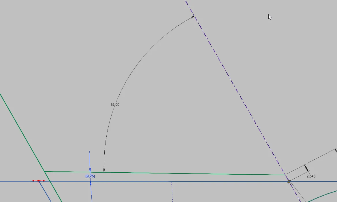
The angle dimension is treated the same way: The functional angle is the one between the collision contour (blue) and the angled end face (green), while the manufacturing-compliant dimension is the one from the end face to the segment centerline (image 1.4).
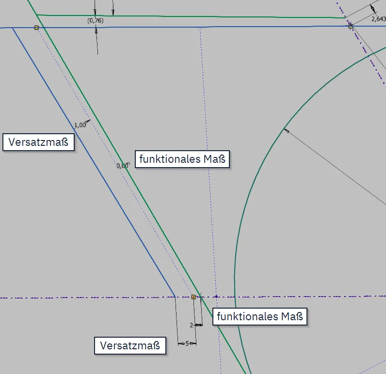
To automate such an arrangement, a functionally dimensioned contour made of construction lines is suitable, from which offset dimensions are set to the actual contour. This solution is demonstrated at the second collision possibility on the left in the image, i.e., the release of the blue segment. The collision contour is now the long green line, and the angled end face is the short blue one. First, as shown in image 1.5a, the angled end face is drawn as a construction line and dimensioned functionally. In this example, again a safe distance of 2 mm and, since no reserve angle should be maintained, an angle of 0° to the collision contour, which in this case could also be a parallelism condition. The actual component contour of the blue segment is then dimensioned controlling from this construction line with offset dimensions.
Now, as shown in image 1.5b, the manufacturing-compliant reference dimensions are set, in this case from the end face line to the centerline of the segment and from the apex of the end face to the center of the joint.
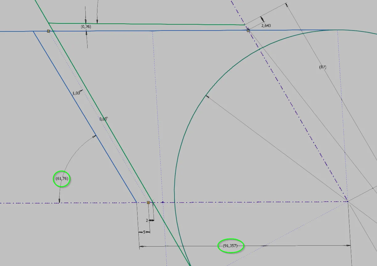
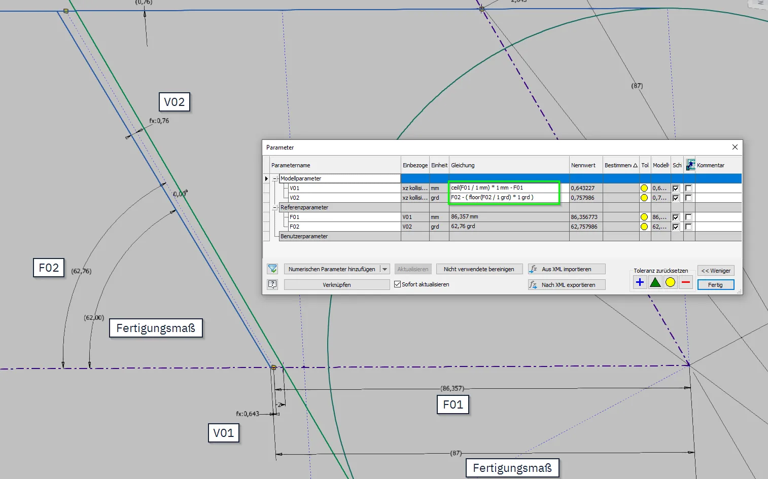
The offset dimensions can now be manually set so that the manufacturing dimensions are rounded to the desired points. If frequent changes are expected, the offset dimension could be automated. For this purpose, the dimensions corresponding to the manufacturing dimensions are set as reference dimensions on the construction line. I have named them F01 and F02 in the example. Now, the values for the offset dimensions can be calculated: The offset dimension of the apex (V01) receives ceil(F01 / 1 mm) * 1 mm - F01 as a formula; this way, it always corresponds to the value that is missing from F01 to reach the next whole number. The units must be specified in these formulas, as the rounding functions work without units. Similarly, the angle offset dimension of the angled end face receives the formula F02 - ( floor(F02 / 1 deg) * 1 deg ), so that the offset dimension always contains the value that is missing to reach the next smaller whole number.
The result is shown in image 1.6: The manufacturing dimensions are automatically rounded to whole numbers, regardless of how the movement geometry of the joints changes due to design modifications.
Desired dimensions
Desired dimensions work similarly to the automated offset dimensions, but instead of the functionally dependent dimension (in the previous example F01 and F02), a controlling dimension is set. This is particularly useful for larger step sizes, for example, when the next larger standard size or catalog size should always be used.
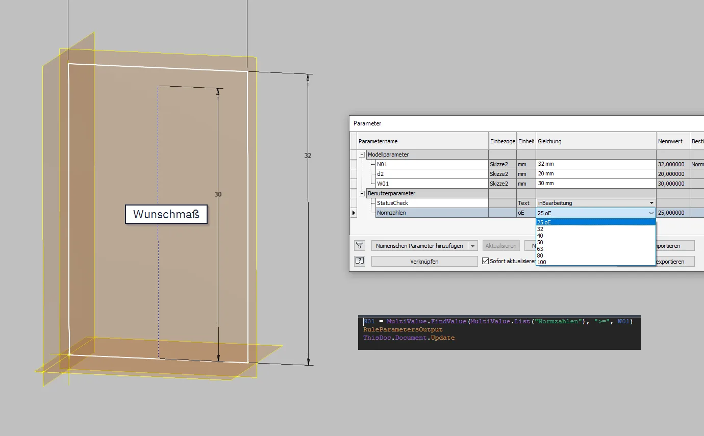
In the first example (image 1.7), the height of the white rectangle (model parameter N01) is to be set to values of the R10 standard series, taking into account the desired value (model parameter W01). The easiest way to do this is to create a numerical multivalue parameter (user parameter standard numbers) without a unit that contains the standard numbers. Then, a small iLogic rule is written that contains N01 = MultiValue.FindValue(MultiValue.List("Standard numbers"), ">=", W01). This one line causes the rectangle height N01 to be set to the next larger value of the list parameter standard numbers from W01. To speed things up, a RuleParametersOutput and InventorVb.DocumentUpdate can be appended.
If several values are to depend on the desired dimension at the same time, a Select-Case statement or an If-ElseIf-... statement could also be used.
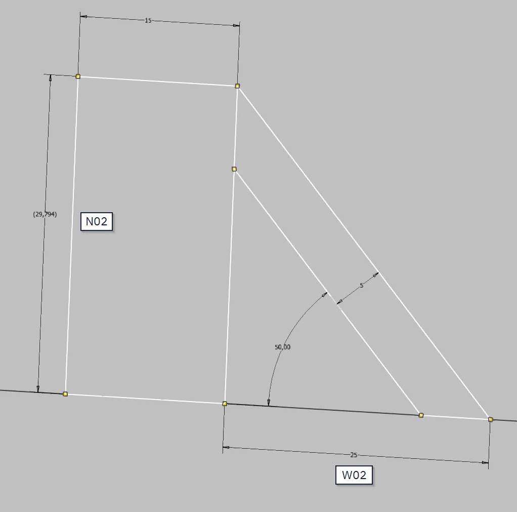
In the second example (image 1.8), there is an angular relationship between the desired dimension and the dimension to be stepped. The dimension W02 is to be specified by the user or environment, while the angle is a design dimension and order-dependent. However, the height of the rectangle should follow the standard gradation as in the previous example. For this purpose, a deviation from the desired dimension is allowed as far as necessary to reach the next standard height.
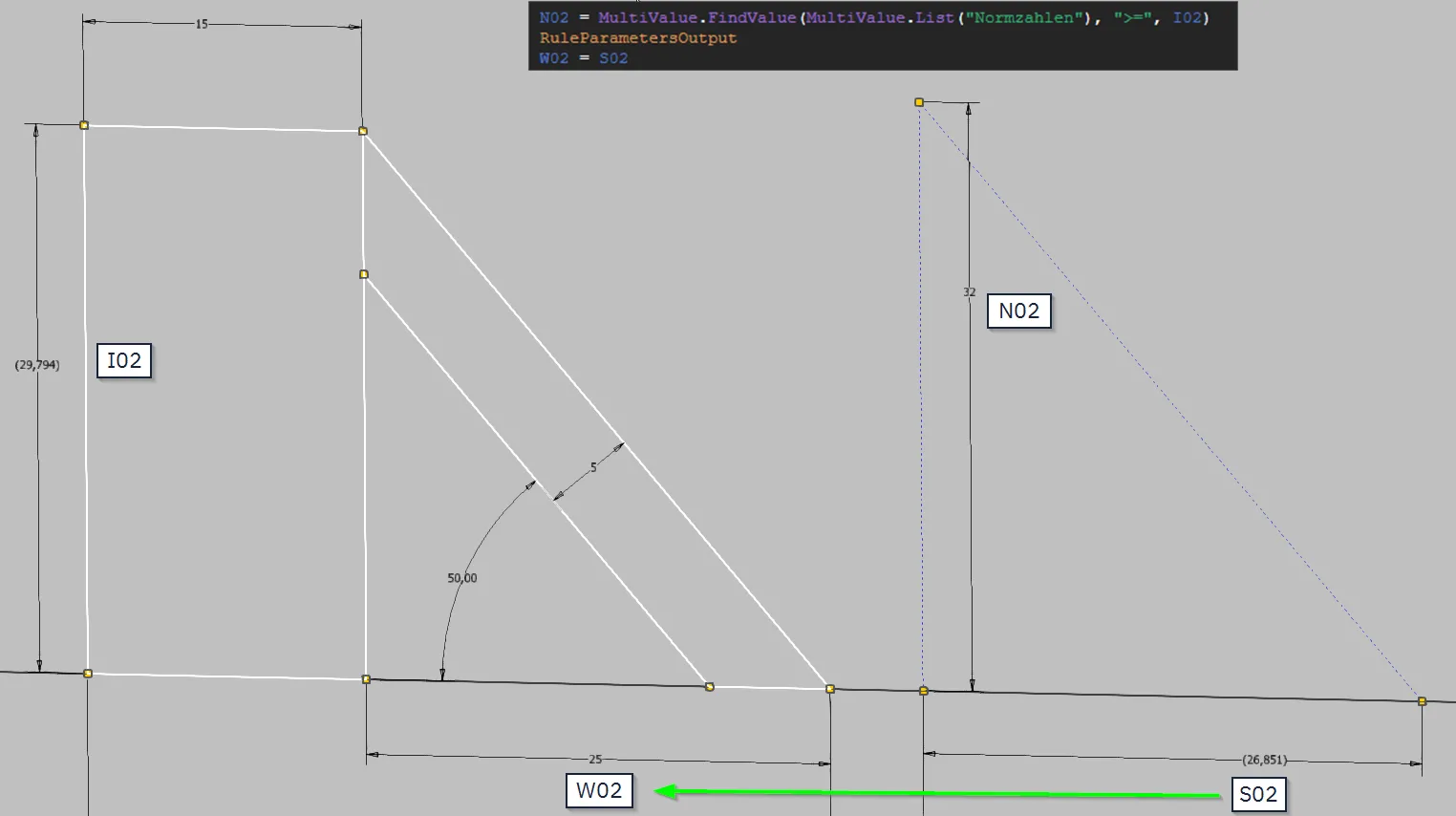
To find an automated solution here, the relevant geometry is doubled as construction lines, as seen in image 1.9. The desired dimension is made a reference dimension in the copy as the target dimension S02, and the dimension to be stepped N02 is made the controlling dimension. The formula is similar to the first example but now depends not directly on the desired dimension but on the indirectly resulting reference dimension I02: N02 = MultiValue.FindValue(MultiValue.List("Standard numbers"), ">=", I02). After determining the nearest standard dimension N02 with the desired dimension and the indirect dimension, the geometry is updated. The target dimension S02 determined in the copy is then transferred to the desired dimension of the component contour; for this, the Parameter command must be used because the shadow copy of S02 still contains the old value in the iLogic rule. Since the input values of the rule do not change after execution, this is not a circular reference; after being set once, the dimension is no longer changed, and therefore, the rule is executed only once.
Conclusion
These examples show that manufacturing-compliant or dimensioning based on standards and catalogs can be easily compatible with the functional dimensioning necessary for stable top-down models. The prerequisite is that the selection logic according to which the manufacturing or catalog dimensions are determined is represented in the skeleton. This can be done with mathematical formulas and functions or with simple iLogic rules. With changes, you save yourself the manual straightening of dimensions and looking up catalog or standard values, thus saving a lot of tedious work.
If you need more in-depth advice on CAD methods, please click on Contact.
You are also welcome to download the short presentation (sorry, only in German) on the topic. It may be used freely in unchanged form, including commercially, provided the source is acknowledged (license: CC BY-ND).
You can also download the model files in the finished state of this tutorial.
Click the links to copy to clipboard
This page: https://r-kon.eu/cad-indirekt-gesteuerte-masse.php
The video: https://youtu.be/9qJfNIOCi0I (Youtube) / https://dai.ly/k1jFhIF6xRPVrBD3zFM (DailyMotion)