
Top-down modeling in 3D CAD
Possible applications, advantages and basics of the top-down method
Links on the topic: The Video about top down modeling at Youtube or DailyMotion and the short presentation (sorry, only in German) as PDF.
Automation of CAD models with the top-down method
These days, there is a lot of talk and writing about digitalization and automation in all possible areas of life. In conversations, however, I sometimes hear " design work can't be automated". However, I don't see it that way. In classic CAD design, too, there is always a lot of repetitive laborious tasks that we can well let the computer do for us, if we CAD designers align our working methods accordingly. One way of doing this is the top-down method.
Top-down modeling is in itself a CAD method that has been known for a long time and is also documented in principle by the manufacturers of 3D CAD systems and supported by means of functions geared to it, although the commitment in this area differs greatly between the makes.
Although it is a very contemporary method and there is a lot of talk about efficiency, in my impression this form of model building has so far tended to lead a niche existence; only a few designers seem to work in this way.
I would like to introduce interested 3D CAD designers here to the top-down method, especially in the form of skeleton modeling, because I find it very exciting and useful, and it can help us increase our efficiency and thus ultimately save our jobs.
The topic itself is somewhat independent of which CAD system you use, because the basic principles apply equally to all systems. I show my examples in Inventor. If something is fundamentally different in Creo, I will mention that in parallel. Top-down modeling itself should be feasible in all common 3D CAD systems, Solid Works, for example, also advertises it (the keyword here is "intelligent assemblies"), but I do not know in detail how it is operated.
What is top-down modeling well suited for?
Top-down modeling, especially skeleton modeling, is good for quickly building consistent, flexible designs that can be seamlessly reused for detailed design, as well as generally creating efficiently customizable assemblies.
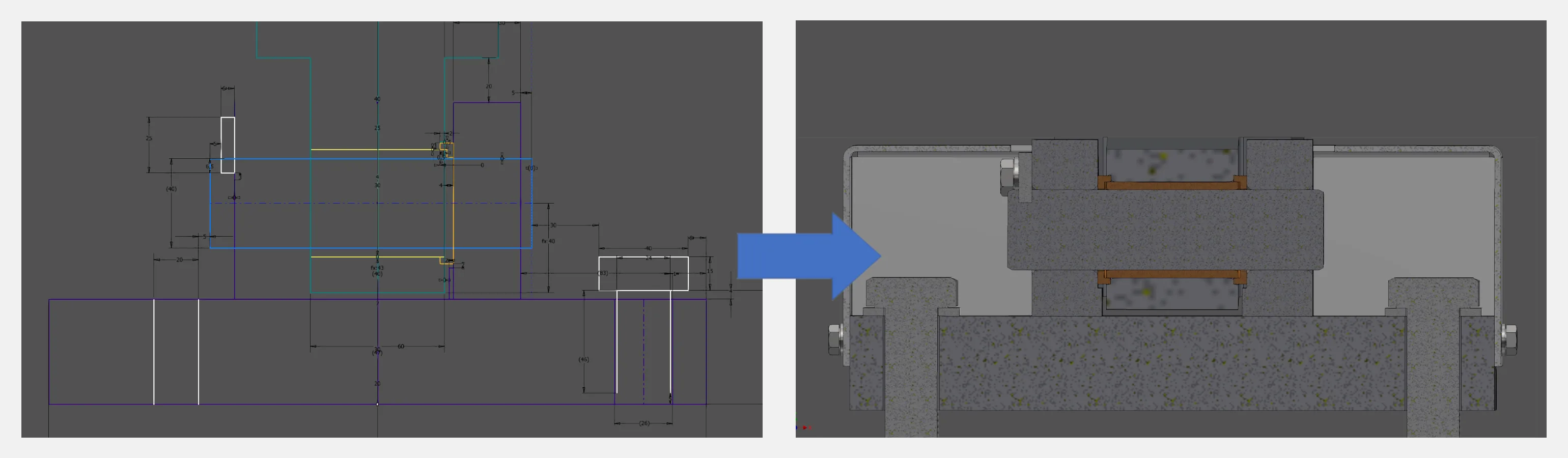
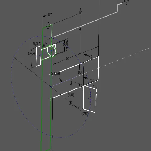
In my opinion, the method is useful for any assembly where parts or subassemblies are interconnected via interfaces, so pretty much any design. Figure 1.1 shows an example of a sliding bearing in skeleton modeling:
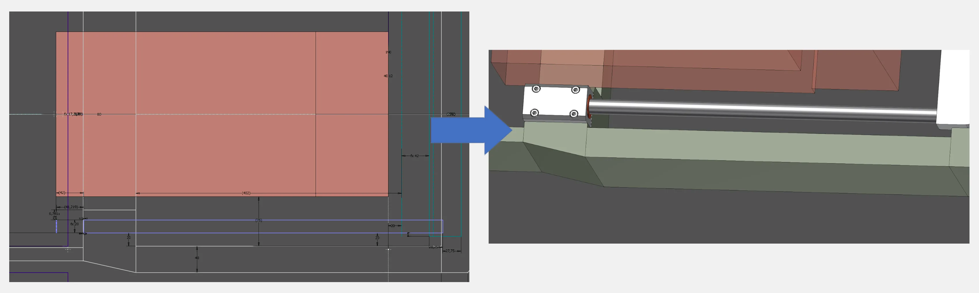
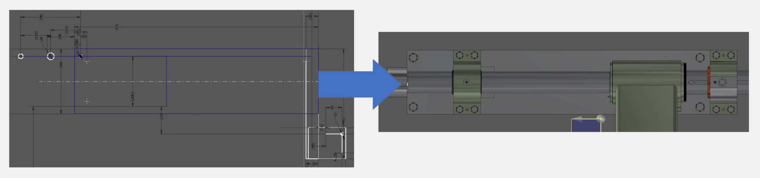
It can also be very useful for synchronizing installation spaces or interfaces of different plant components. In the case of Fig. 1.2, it was necessary to design around the red interference volume, and in the case of Fig. 1.3, to continue using an existing bolt-on surface:
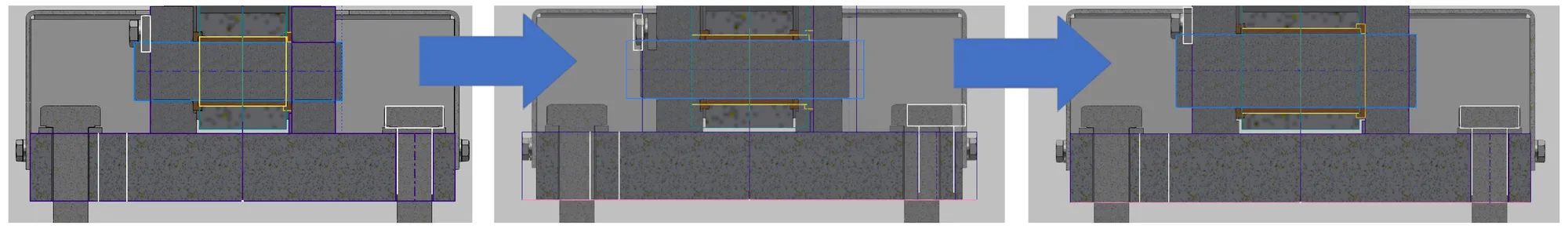
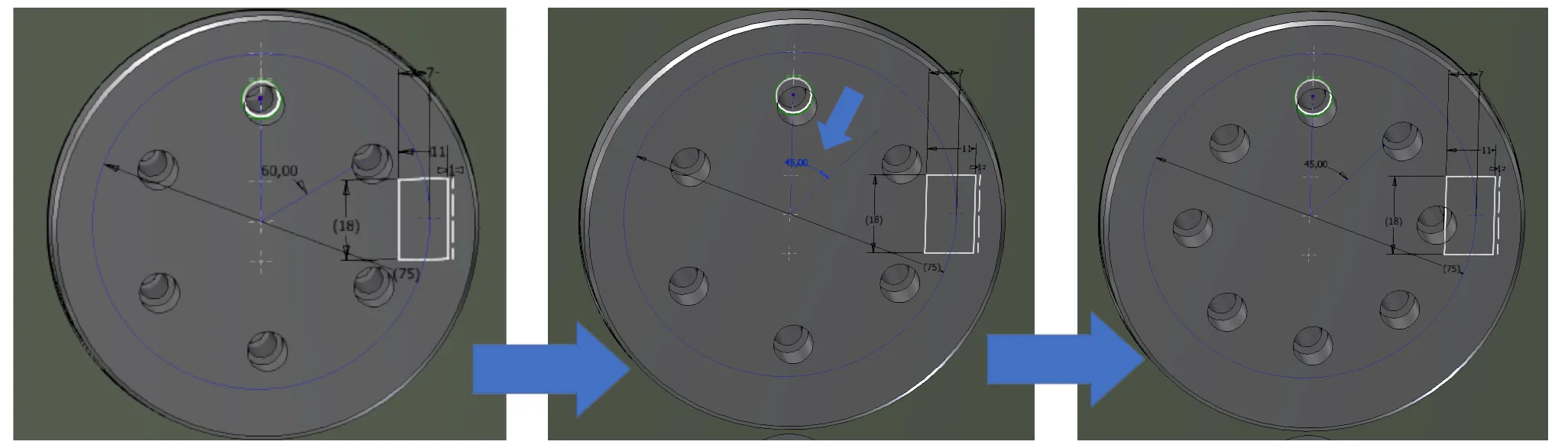
Top-down modeling is particularly advantageous when models are to be modified after initial creation. If dimensions are varied in the course of the design phase, or if a customer wishes to make adjustments after the design has been presented, the design can be adapted with little effort and with relative certainty that all parts will still fit together after the change. Figure 1.4 shows the modification of a slide bearing by changing some dimensions in the skeleton.
The method also saves a lot of work if you want to execute a basically identical design in different sizes or with dimensions adapted to the order, or if you want to scale it as a whole. In a well-structured top-down model, adjustments can be made in all these scenarios with very little effort by entering just a few dimensions, which are then consistently applied to all dependent parts.
Common use cases are for example:
- Bearing arrangements in which housings, covers, shafts, etc. depend on the choice of rolling or sliding bearing
- Welded structures consisting of dimensionally interdependent parts
- Moving parts whose interfaces depend on different states of movement
- Designs for which installation space limits must be observed
- Bolted joints (Fig. 1.5)
The top-down method is therefore particularly suitable for:
- Coherent modeling of assemblies, in which different parts or subassemblies have commen interfaces
- Fast creation of flexible, consistent drafts
- Assemblies, that are to be scaled or dimensionally modified after their creation
How does top down modeling work?
Top-down modeling basically works in such a way that elements are defined on the respective higher hierarchy level in the tree hierarchy of the assembly models, which are then used as the basis for the next lower level. So-called skeleton parts are used for this purpose. Each assembly has a skeleton part in which the dimensions, geometries, relationships and states important for this assembly are defined, usually in the form of sketches or working elements (Figure 2.1). In principle, surface or even solid bodies are also possible in the skeleton, but I think they usually have more disadvantages than advantages. For plant layout planning sometimes a very rough skeleton is sufficient, with which only planes, axes or coordinate systems are transferred for the location of the individual plants and interfaces. For machines and equipment, on the other hand, it can be useful to define everything down to the thread sizes in the skeleton. Unfortunately, standard parts cannot be easily automated in Inventor and Creo; you still have to change them manually or write larger scripts.
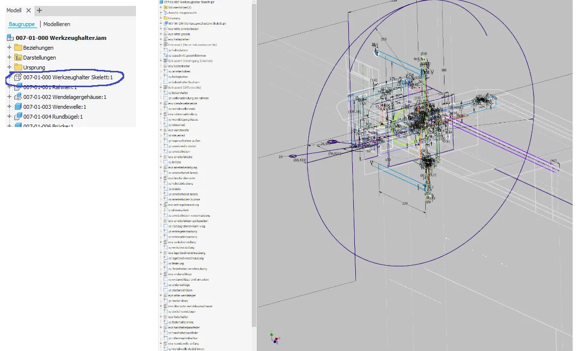
When many sketches are visible, it looks very confusing at first sight. Normally, therefore, you only make visible the sketches that you need at the moment, which is then usually very manageable (Figure 2.2 and 2.3):
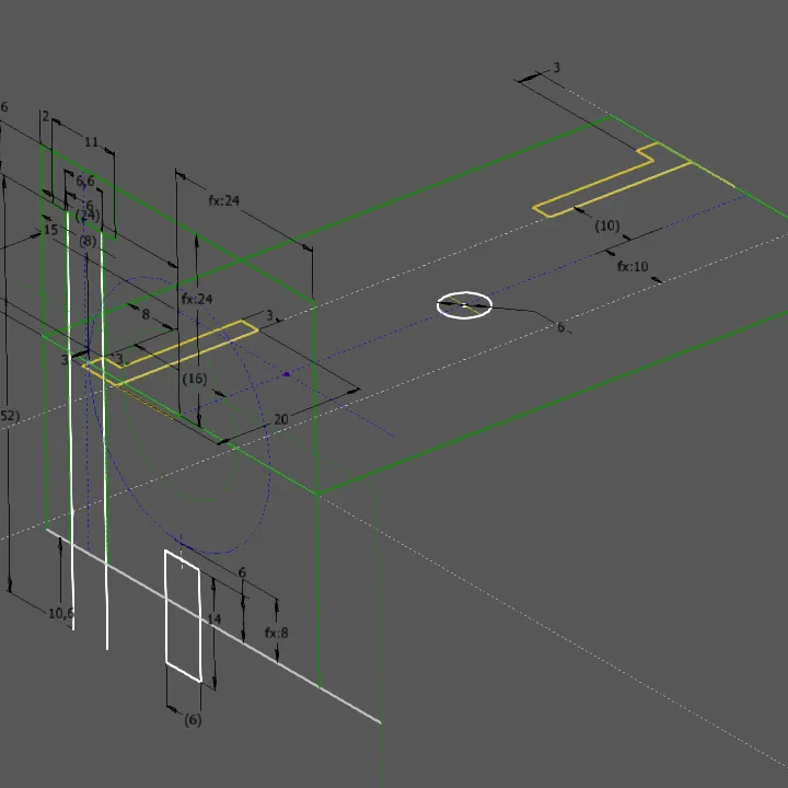
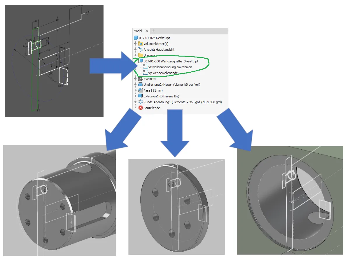
The parts or subassemblies built into this assembly then inherit the relevant elements of the skeleton as an external references, so to speak, and are based on them. In Inventor, the function used for this is called "derived part" and is very convenient, in Creo it is the combination of "publish geometry" and "copy geometry" and is not quite as convenient. In both cases, you select only the elements from the skeleton that are needed in the part. A useful side effect is that you can usually also see the interface of the adjacent parts in the single part. Figure 2.4 illustrates the information flow from the skeleton sketch via the function "derived part" into the single parts.
All dimensions that have been defined in the skeleton are correspondingly no longer defined in the individual part or subassembly, but only transferred.
This creates a redundancy-free overall model, because interface dimensions for the connection of several parts no longer have to be defined individually in each part and transferred manually, but are defined once in the skeleton for all parts / subassemblies involved.
A particularly large amount of redundant work can be saved in this way on:
- Bolt connections
- Welded parts
- Bearing assemblies
- Mated connections
- Covers and lids
- Movable parts with several relevant positions
- ...
Advantages of top down modeling
The advantages of top-down-modeling over indepenent parts are similar to those of a 3D-derived drawing over a 2D-created drawing: In a 3D-derived drawing, you have to make changes only once in the part and then all views, no matter how many, are updated by the system, whereas in 2D you would have to manually change each view individually. In an assembly created using the top-down-method, you only have to make changes once in the skeleton and the system updates all derived parts, where in a conventional assembly model you would have to manually change each part individually.
Time saving
- During model creation, interfaces are created only once for all affected parts together.
- When dimensions are changed or scaled, affected dimensions are edited only once.
- You only need one model structure for a product, which contains the current state of development, and you can derive different sizes and variants from it.
Error prevention
- Errors in the transfer of dimensions between parts are eliminated because each dimension exists only once.
- Deviations due to modeling or assembly errors are easily detected by overlaying them with the skeleton.
- Interrelationships are defined functionally as they logically belong together.
- If several people are working on a project, the interfaces between them are continuously synchronized by the skeletons.
High flexibility of drafts
- Assembly models can be built completely without knowing input variables exactly, because subsequent updating is easy.
- For simulations or visualizations, basic geometries can be derived as coarse bodies without first having to create and assemble individual parts.
Improved assembly organization
- Unstable placement references for imported models can be replaced by working geometry in the skeleton.
- Different states of movement can be clearly displayed and edited in context on the basis of the existing geometry.
- Preset connection dimensions of the environment can be used as input values in the skeleton and thus reliably respected.
- Detection of potential common parts as well as transfer and validation of interface dimensions is very easy in the skeleton.
Disadvantages
Of course, everything has its price: this method also has disadvantages, otherwise everyone would already be working with it:
- Very careful selection of references required during model creation.
- Very careful attention must be paid to geometrically stable sketches
- Effort for functional changes can be greater (e.g. round part becomes angular, participation of parts at interfaces changes, ...)
- Effort for familiarization with the method as well as with a top-down structure created by other designers
- Origin of dimensions and geometries must be searched over the hierarchy levels, if something is to be changed
- Some important fundamental rules must be followed in a compellingly disciplined manner during model creation
- Troubleshooting may be required when changes are made because elements fail due to small errors, often in referencing
Intuitively, users suspect disadvantages for processing speed when loading models, but there are no disadvantages here to my knowledge: In terms of computing performance, top-down models are usually not worse but rather better than conventional models due to the significantly reduced number of variables and necessarily cleaner structure. In any case, I myself have not experienced in several years that models have become slow as a result.
Prerequisites for the application of top-down modeling
- Sound knowledge of the CAD system used is necessary for the creation of stable top-down models.
- In general, it must be bindingly defined up to which level of detail work is carried out in the skeleton.
- Conventions for the structure of assemblies and the identification of sketches and working elements must be created and very consistently adhered to.
- Existing conventional models may need to be hooked into the top-down structure or recreated for it.
- For adapting existing top-down models, on the other hand, all that is needed is basic knowledge, instruction in the method, and patience in finding the required dimensional sources. However, the willingness to apply a fundamentally different way of working must be present.
Conclusion, closing words
Despite counteracting effects due to the elimination of referencing errors or additional work for fundamental functional changes to geometries, the top-down method, properly applied, brings a great improvement in efficiency in many cases. So design work can be automated to some extent after all, there is quite a bit of laborious work that we can avoid as a result.
So, this was the first section here in the "CAD tutorials" section. If there is positive feedback on it, I will add respectively translate more chapters.
If you need more in-depth advice on CAD methods, please click on Contact.
You are also welcome to download the short presentation (sorry, only in German) on the topic. It may be used freely in unchanged form, including commercially, provided the source is acknowledged (license: CC BY-ND).
Click the links to copy to clipboard
This page: https://r-kon.eu/cad-top-down-modellierung.php
The video: https://youtu.be/ObaCM5vhklA (Youtube) / https://dai.ly/x8pbl1m (DailyMotion)