
Set size grading for elements
How to set standard sizes for elements in the model
Links on the topic: The Video on setting size grading for model elements at Youtube or DailyMotion and the short presentation (sorry, only in German) as PDF.
Consider size gradations for standard or catalog parts in the skeleton
When standard and catalog parts are installed in skeleton assemblies, their connection dimensions must be represented in the skeleton in order to control the adjacent manufacturing parts. However, the skeleton dimensions have no influence on the models, which are mostly obtained from libraries or suppliers. It is therefore advisable to ensure at least that only those sizes can be set in the skeleton in which the part in question is actually available. In addition, it should be ensured that all dimensions of a standard or purchased part belong consistently to the same size. I will show two ways to achieve this: The use of list parameters and control via iLogic based on an entered value.
Preparation for both variants: Name dimensions sensibly
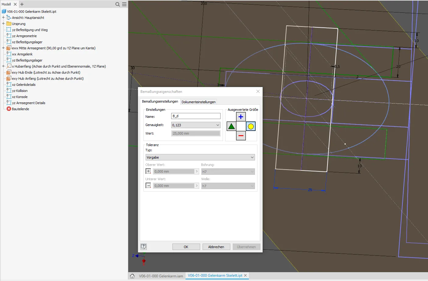
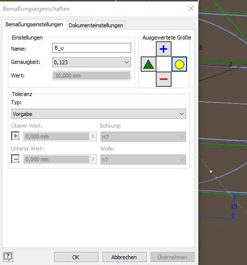
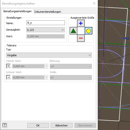
In the first step, all dimensions relevant for size grading, in this example the diameter, the protrusion and the clearance of the bolt, are appropriately named (Figure 1.1 to 1.3). It is advisable to use a base name per element ("B") and append the variable names from the standard or catalog.
The quick solution for simple cases: List parameters
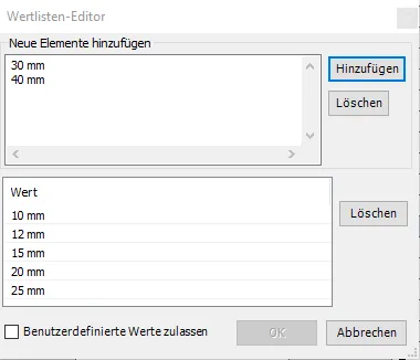
The simpler, but not so powerful variant is the definition of the nominal size as a list parameter. Most will have learned this during their training or in the Autodesk tutorials. In the context menu, "Create multiple values" is selected and then a list is created with the sizes that should be selectable (Figure 2.1, 2.2). The named dimensions can also be declared as key parameters on this occasion so that they are easier to find later.
In the list, units can be specified, but it is usually better to enter the list values without a unit, because some iLogic and API functions react poorly to letters in the list.
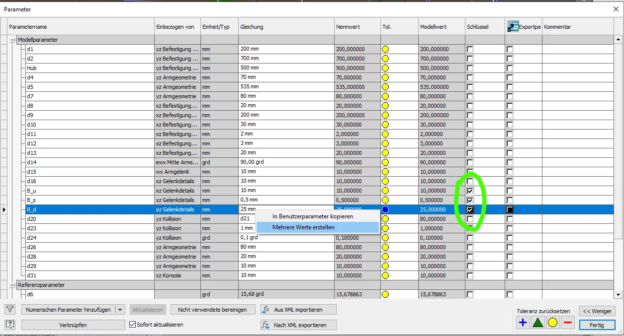
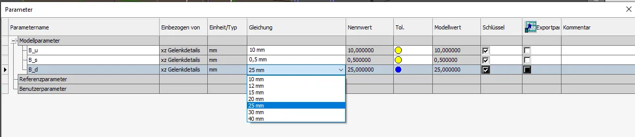
The dimension can now be set in the parameter list via dropdown to one of the predefined values. Caution: In the model, dimensions can still be entered that are not on the list! It must be communicated to other users that the parameter list is to be used to control the model, for example by annotations or a corresponding manual.
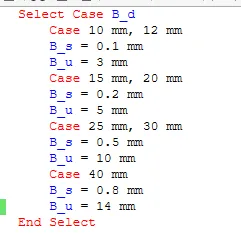
If other dimensions belong to the element that is only available in increments, these can be set depending on the list parameter using iLogic. Usually the "select case" statement will be the means of choice, but also constellations with "if" or "while" are conceivable. Depending on the diameter, the two other named dimensions are set as shown in Figure 2.4. The clearance and the protrusion are equal for groups of successive nominal sizes. Such groupings occur in many standards.
In real life, I would define the required minimum protrusion as a parameter and adjust the actual protrusion dimensions with an additional select-case block from the width of the joint tabs plus the minimum protrusion to the available lengths of the bolt. For clarity, I have omitted this in this example.
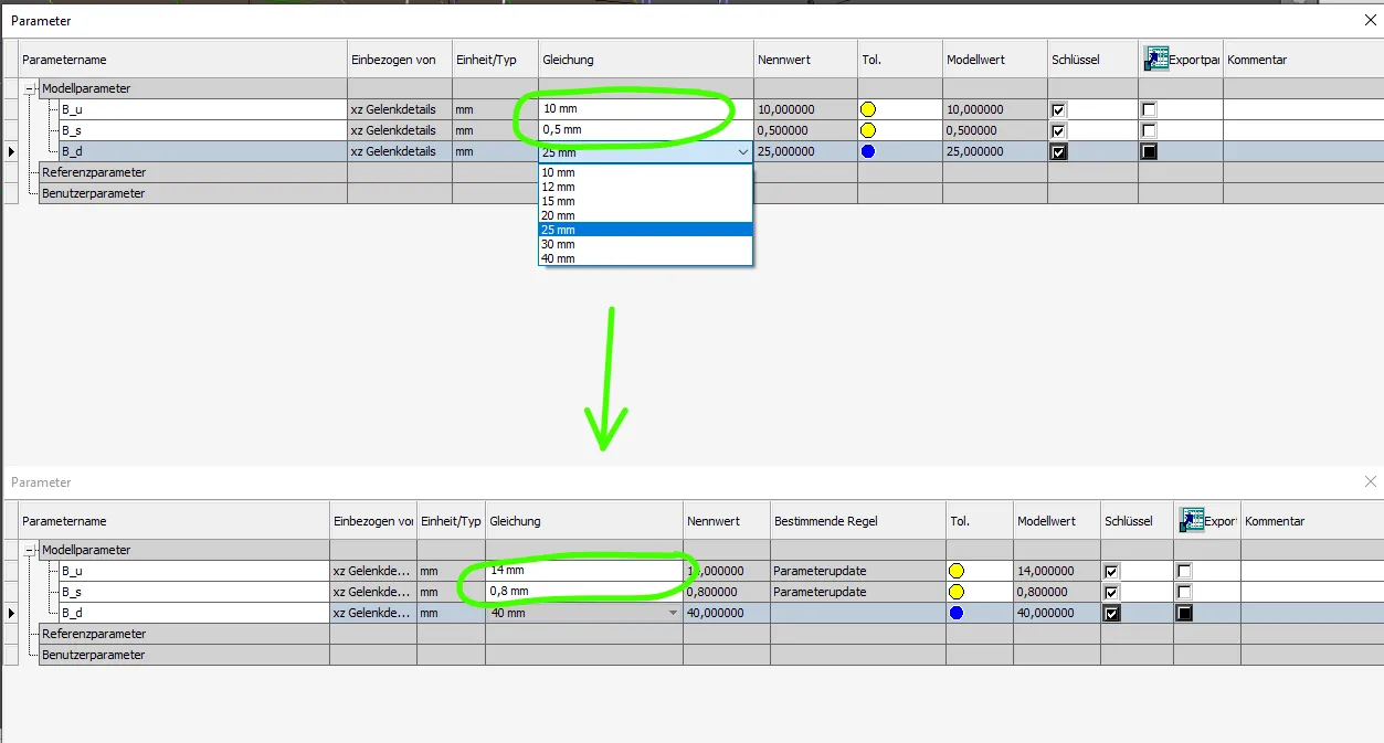
With this small rule, which is executed automatically with every change of the input parameter, all three dimensions relevant here are changed simultaneously and consistently, provided that the user uses the dropdown in the parameter list as shown in Figure 2.5.
The good solution for more complex parts: Control with input value and iLogic
The foolproof and clearer method is to build the size gradations completely with iLogic and a separate input parameter or dimension. The input parameter is not strictly necessary, as the entered parameter itself can also be processed with iLogic. However, this is very opaque, the user does not see why the entered value changes "by itself" when updating the model. Therefore, I generally recommend creating an additional geometry element in which the user enters his desired value. The input value remains visible and is separated from the automatically set value. This method can also be used to create a "crooked" input or reference dimension with "round()" into a dimension straightened to certain decimal places or decimal places.
For the input of the diameter of the bolt required by calculation, an additional circle is created in the sketch, the diameter of which the user can choose freely. The dimension is given a name, for example the variable name of a calculation result "d_erf". (Figure 3.1)
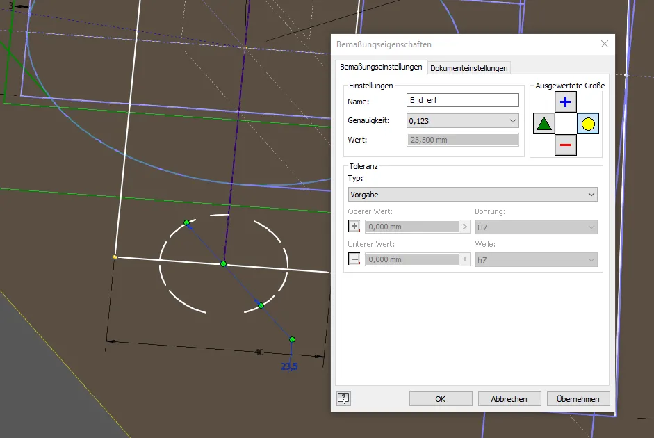
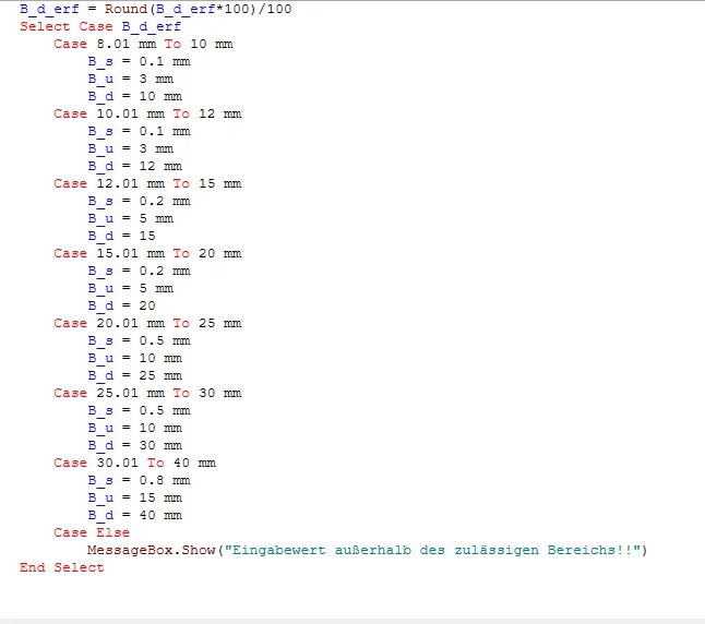
The input value "d_erf" is now processed with an iLogic rule. Using "select case" (Figure 3.2), the bolt diameter, protrusion and clearance are set depending on which range the required diameter is in. The required diameter from a calculation is a minimum value, so the values in the "select case" block are chosen so that they are always rounded up. To avoid having the input value between the individual ranges when entering more decimal places than provided for in the case block, I round to 2 decimal places at the beginning. One could also use the same integer value for the beginning and end of the adjacent ranges, as Select Case only executes the first applicable block exactly. As mentioned above, the total length would normally be set with an additional case block instead of just defining the protruding ends here.
In this case block, you could also issue a warning with "case else" and "MessageBox.Show" if the input parameter is outside the standardized range.
If only the value closest to the input value with a certain decimal accuracy or decimal place is to be searched, it can be multiplied by powers of ten as shown, rounded with "round()", and then divided again (or in reverse for decimal places) and assigned to the model parameter.
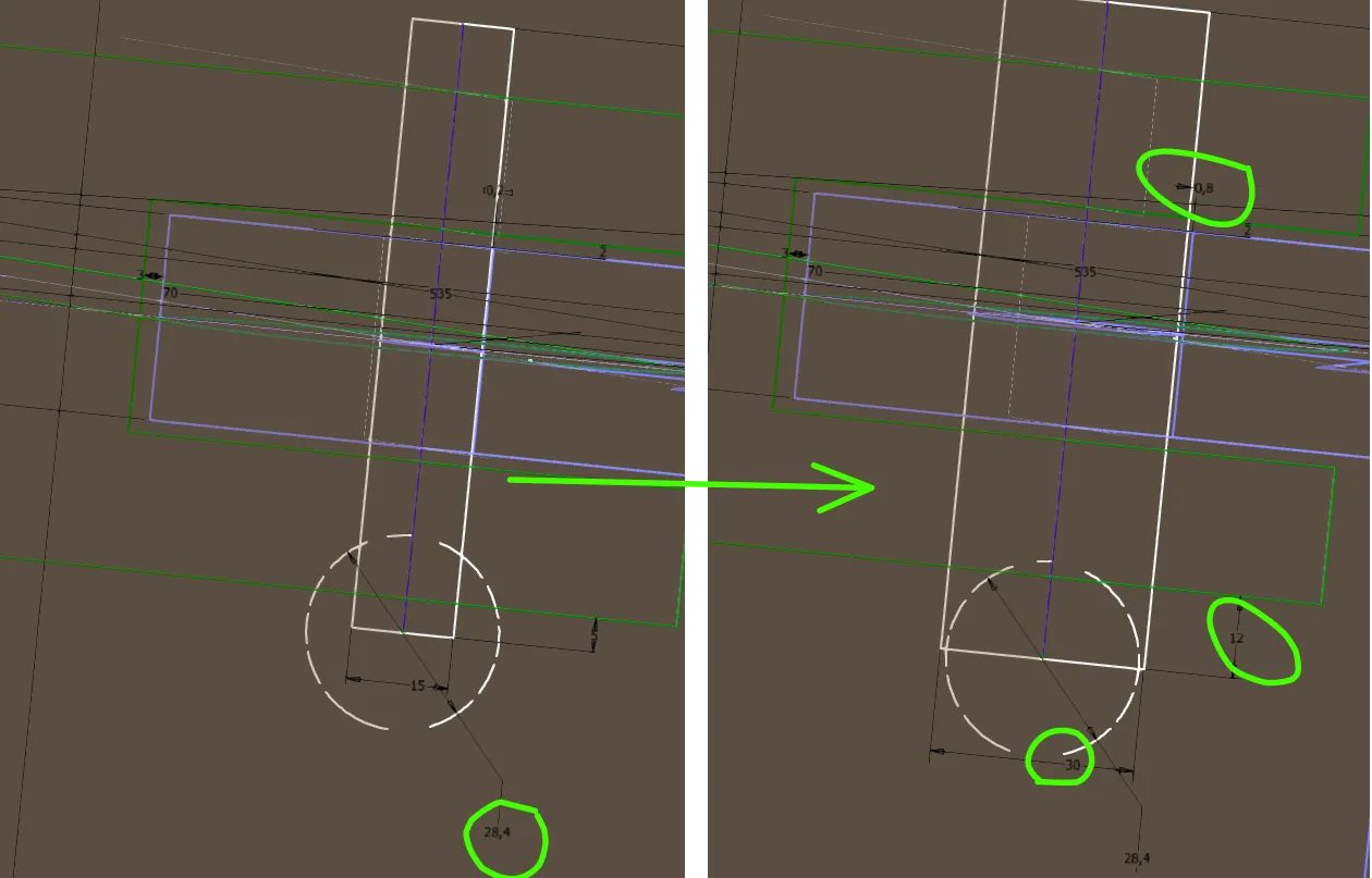
If the user now enters a desired minimum bolt diameter in "B_d_erf", the iLogic rule sets all defined properties of the bolt to the next higher standard size when the model is updated, as shown in Figure 3.3.
Conclusion
With the methods shown, dimensions from catalogs and standards can be stored and linked in a variety of ways in a part or assembly. Properties of the model such as weight can also serve as input variables, for example to automatically set attachment holes to the correct size. Size-dependent construction elements can also be installed that are only to be present in certain size ranges.
If you need more in-depth advice on CAD methods, please click on Contact.
You are also welcome to download the short presentation (sorry, only in German) on the topic. It may be used freely in unchanged form, including commercially, provided the source is acknowledged (license: CC BY-ND).
You can also download the model files in the finished state of this tutorial.
Click the links to copy to clipboard
This page: https://r-kon.eu/cad-groessenstufung-festlegen.php
The video: https://youtu.be/-1iDHxNWh3Y (Youtube) / https://dai.ly/kkApUsvaNQvYL3CZYOa (DailyMotion)