
Designing wedge adjustments with sketches
How stroke, end positions and geometry of wedge adjustments can be easily designed in sketch skeletons
Links on the topic: The Video about wedge adjustments in the sketch skeleton at Youtube or DailyMotion and the short presentation (sorry, only in German) as PDF.
Design wedge adjustments with as little effort as possible
Wedge adjustments have a number of different geometric parameters that influence each other. Usually, a desired adjustment stroke and an available installation space are given as input quantities, as well as loads and self-locking specifications that narrow down the possible angle range. However, the exact angle, the length of the involved wedges, the overlap in the end positions and the position of the stroke must be freely defined and influence each other to a large extent. If the components are modeled individually, changes to the wedge parameters mean manually adjusting several involved models and installation conditions in the assembly. Adjustments thus become a time-consuming and error-prone process.
Therefore, it is very useful to have a design sketch in which the variable parameters are clearly accessible and all relevant results of changes made become immediately visible. Following the proven principles of top-down modeling, all affected components follow this design sketch and are thus always consistent because any change is automatically transferred to all involved components.
Movement specifications of the environment
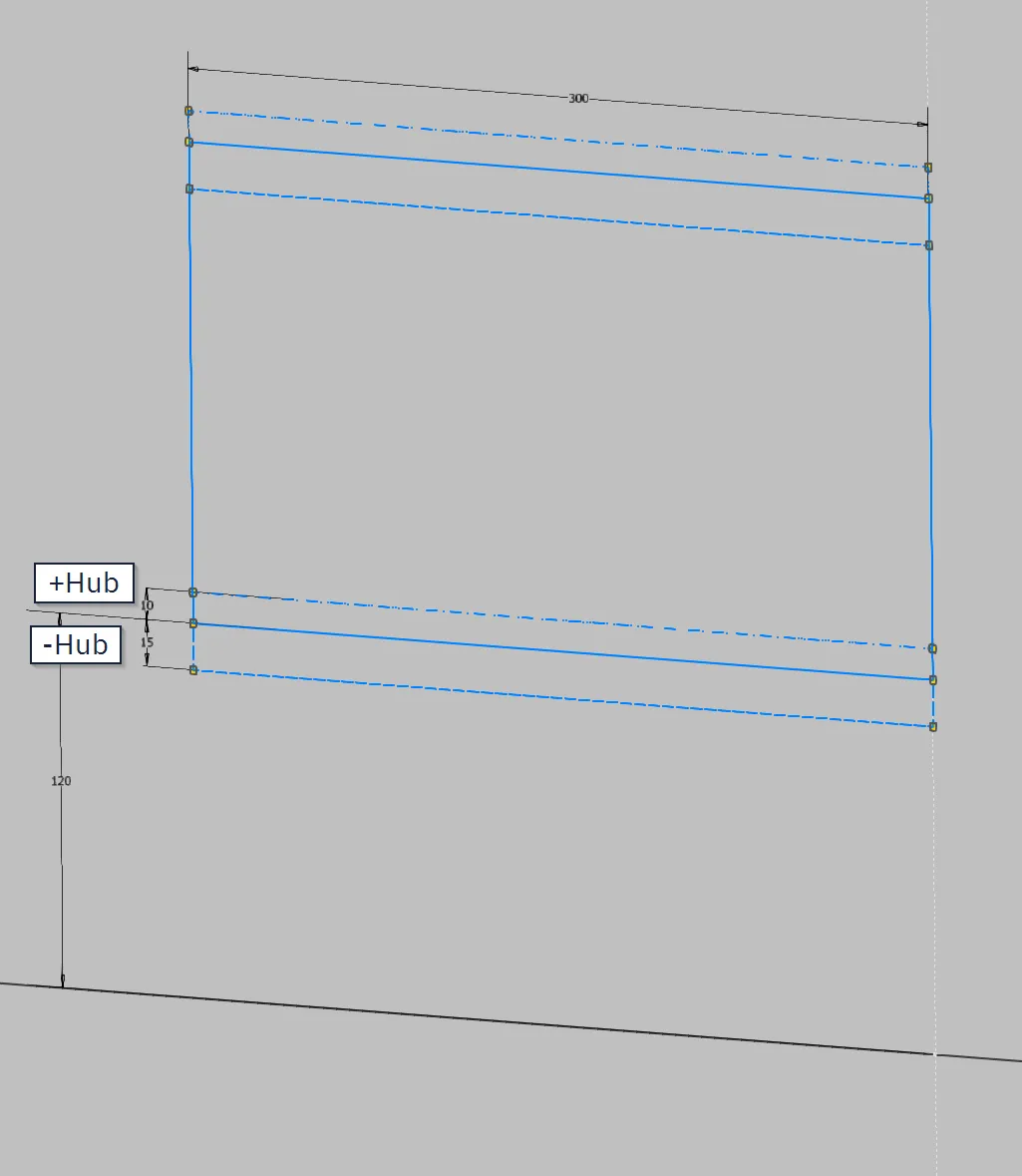
Before the wedge adjustment can be designed, the requirements must be sketched. The component to be moved by the adjustment must be drawn in all relevant positions. In the example, an assembly with wedges is to be raised or lowered against gravity. Due to its own weight, guides in the opposite direction can be omitted. The assembly is shown in a middle position, which can be considered as the "standard position". From this position, there should be a positive and negative adjustment stroke. Wedges are fixedly mounted on the underside of the assembly, and a horizontally movable wedge is to be guided underneath. Hydraulic cylinders or adjusting screws would be conceivable as actuators.
The standard position is drawn in the example (Figure 1.1) with full lines, the upper end position with dashed-dotted lines, and the lower one with dashed lines in the same color.
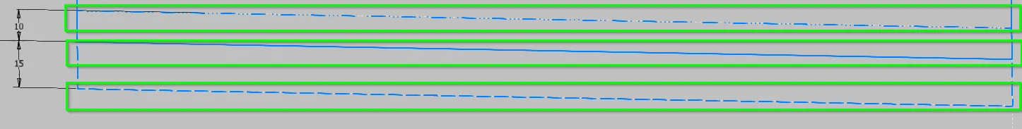
In the sketch for the wedge adjustment itself, the relevant lines of the environment are first projected. In the example (Figure 1.2), this is the connection surface for the fixedly mounted wedge in all considered positions. The side lines of the standard position can be useful, but do not necessarily have to be used.
Represent design data of the wedges
First, we draw the fixedly mounted wedge on the underside of the component to be moved. The dimensions important for the design are dimensioned and set to approximately suitable values. In this example, the height of the thin side of the wedge is important (as thin as possible, but not too thin), as well as the length of the wedge, which is set to slightly smaller than the mounting surface. The wedge should be centered on the connection surface and has a slope of about 10° according to calculations. It gets its own color and, because the standard position is shown, full lines. The vertical position of the wedge remains variable for now.
A horizontal movable actuator wedge is drawn to match this wedge, with its own color and also full lines. The contact surfaces of the two wedges are set to be collinear, and the actuator wedge also receives a thickness at its thinnest point and a length for now so that the lines do not run away. For now, it remains horizontally and vertically movable, as its vertical position is only determined by the lower end position and its horizontal position should remain movable during design in order to illustrate movement. The result shows Figure 1.3.
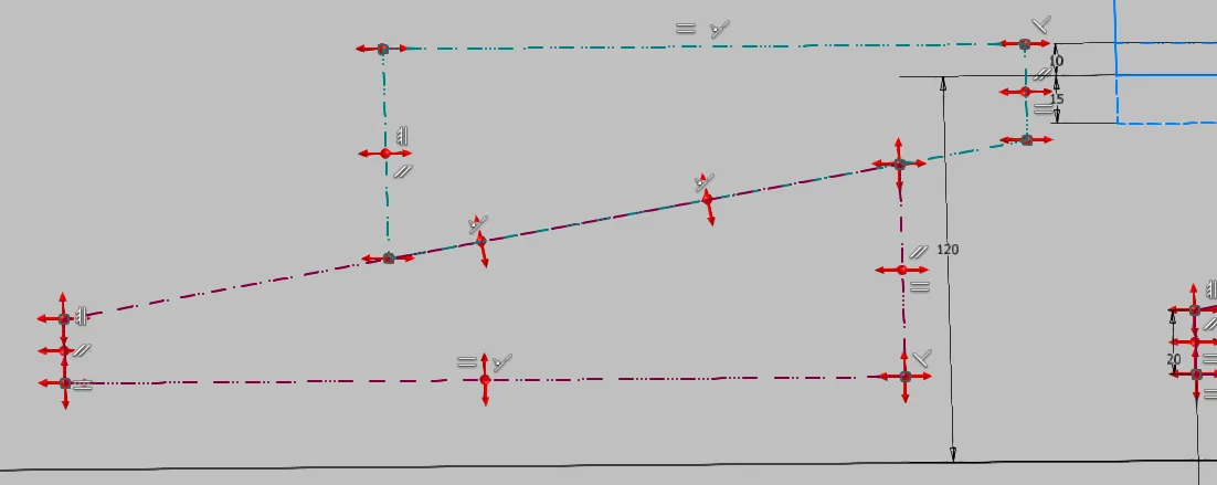
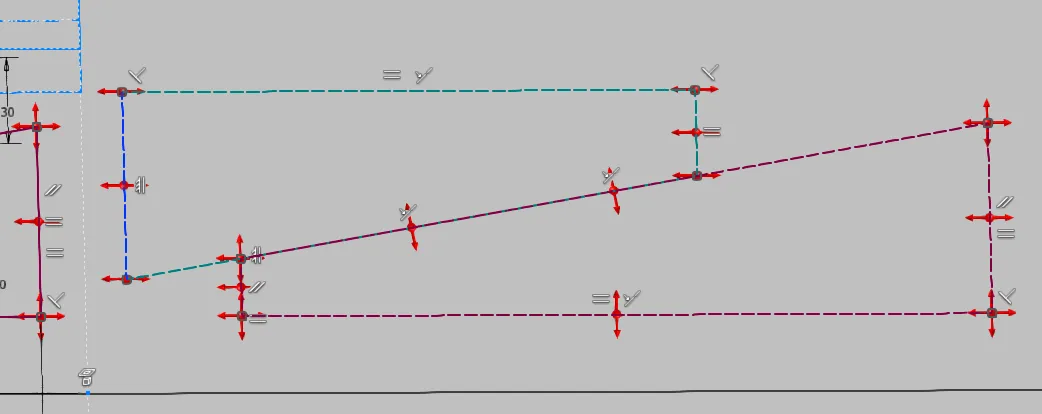
Next, copies of the two wedges are drawn for each end position as shown in Figures 1.4 and 1.5. Each copy receives the color of its template. For clarity, the two copies can be drawn next to the installation location and only moved to the installation location at the end with restrictions. The line type of each end position is used for all copies assigned to this end position. The dimensions of the wedges are set equal to the template. The undersides of the horizontally movable wedges are set collinear for all 3 specimens, and the upper sides with the respective counter-contour of the fixed mounted wedge. The fixed mounted wedges are set collinear with their upper side to the corresponding mounting surface of the end position and only aligned horizontally with the template at the end, e.g., by collinearity with a vertical end line. The end position wedges are thus completely defined, and only the wedges for the standard position can still be moved.
Dimensioning wedges
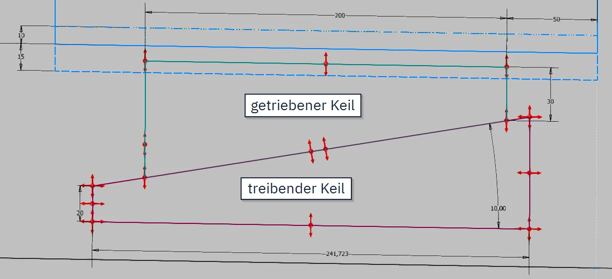
With the end position contours superimposed in this way, you can now specify how far the wedges should overlap in the end positions. In the example, the length of the driving wedge is changed to the reference dimension and a dimension for the overlap or the reduction of the overlap in each end position is set. Here I take the distance to the flat side of the actuating wedge in the lowest position and the distance to the high side of the actuating wedge in the highest position, as shown in Figure 1.6. The height of the underside of the wedge and the length of the actuating wedge are determined by these two dimensions and can only be directly influenced by changing the environment or the wedge thickness.
From this point on, the wedge pair of the standard position can be used for realistic simulation of the movement by pulling. If this degree of freedom is no longer needed, the upper wedge can be set collinear with the mounting surface in the standard position.

Now all design values of the wedge adjustment can be adjusted arbitrarily to find the optimal combination. By adjusting the angle and wedge thicknesses, the required installation space in height can be controlled, and by adjusting the angle, wedge length, and overlap, the installation space in width as well as the stroke. The input values, for example, the stroke to be performed, can of course also be adjusted.
The adjustment path of the driving wedge can be used as an input quantity for the design of, for example, a cylinder. Then the stroke of the actuator always fits the wedge geometry. The components are derived as usual and installed in the assembly with realistic installation conditions, possibly with position views, so that the involved components always fit together, even after changes.
Conclusion
This example is deliberately kept simple in order to present the principle quickly and clearly. Of course, multiple wedges, inclined bolt guides, running fasteners, clamping devices, or countless other similarly functioning motion mechanisms can also be designed in this way. The crucial point is that a situation contour is drawn for each relevant position and the resulting multiple instances of the same components are dimensionally synchronized. I hope that this guide helps some designers in their work.
If you need more in-depth advice on CAD methods, please click on Contact.
You are also welcome to download the short presentation (sorry, only in German) on the topic. It may be used freely in unchanged form, including commercially, provided the source is acknowledged (license: CC BY-ND).
You can also download the model files in the finished state of this tutorial.
Click the links to copy to clipboard
This page: https://r-kon.eu/cad-keilverstellung-entwerfen.php
The video: https://youtu.be/WwJPTcy2ekY (Youtube) / https://dai.ly/k79H11Ezr5cw14D3bMI (DailyMotion)