
Control round patterns with skeleton
How to create and control round patterns, drilling patterns and screw connections for multiple parts in the skeleton
Links on the topic: The Video about skeletton controlled round patterns at Youtube or DailyMotion and the short presentation (sorry, only in German) as PDF.
The advantages of skeletton controlled round patterns and screw connections
Many connections between components are based on patterned elements. The input parameters of the patterns are usually very manageable: For the round pattern, radius, start angle, increment angle and, if less than 360°, the end angle are usually sufficient. In addition, a cross-section is usually required to determine the pattern elements. The synchronisation of these few values across the affected parts determines the assembly capability of the assembly. The manual transfer between the parts means unnecessary risk of error and avoidable drudgery.
Create round patterns and screw connections in the sketch skeleton
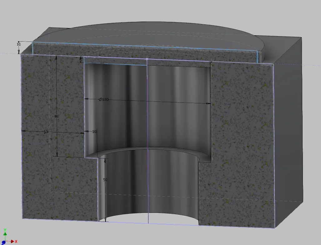
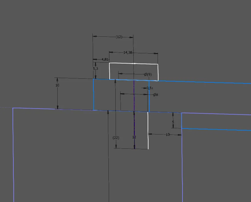
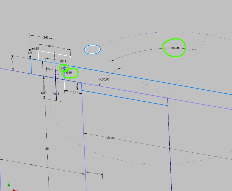
First, it must be determined which information is needed for the pattern elements and the pattern itself across multiple parts and how these are causally related. In the case of screw connections, as in this example, it makes sense to first draw a cross-section as shown in Figure 1.2. A half view is sufficient, the centerline is required. In cross-sections with countersinks or stepped holes, it may be useful to draw the cross-section on a plane rotated by the start angle. The relationship between thread, through hole, possibly countersink and their depths can be well represented in the cross-section, in addition, the suitable edge distance for the hole circle diameter can be indirectly chosen with the diameters of the holes and screw heads. Also possibly to be considered assembly space, for example for sockets should be drawn and referenced in this cross-sectional view. If the pattern is to be symmetrical to a plane, it is advisable to define the start angle as half increment angle or increment angle as double start angle.
In this example, the outer diameter of the cover is dimensioned from the diameter of the screw head so that there is still an edge left for each screw size. To give the cover an outside dimension without decimal places, there is the reference dimension 12 above the screw head. The controlling dimension 4.81 is set so that the reference dimension is even. The center of the screw connection results from a necessary distance of the thread from the bearing hole (dimension 10) and the screw diameter. The through hole is dimensioned relative to the thread line and made visible by a reference dimension (9). This ensures that the through hole is always larger than the thread, even if the user forgets to set the correct diameter for the thread size. If the through hole were directly dimensioned, an unmountable part could be manufactured due to this fluke error.
The thread depth is automatically calculated according to the well-known rule of thumb 1.5*d. This results in the minimum required screw length, which can be read directly at reference dimension 22. The standard depths of threads are chosen for common sizes so that here always fits the next larger screw length.
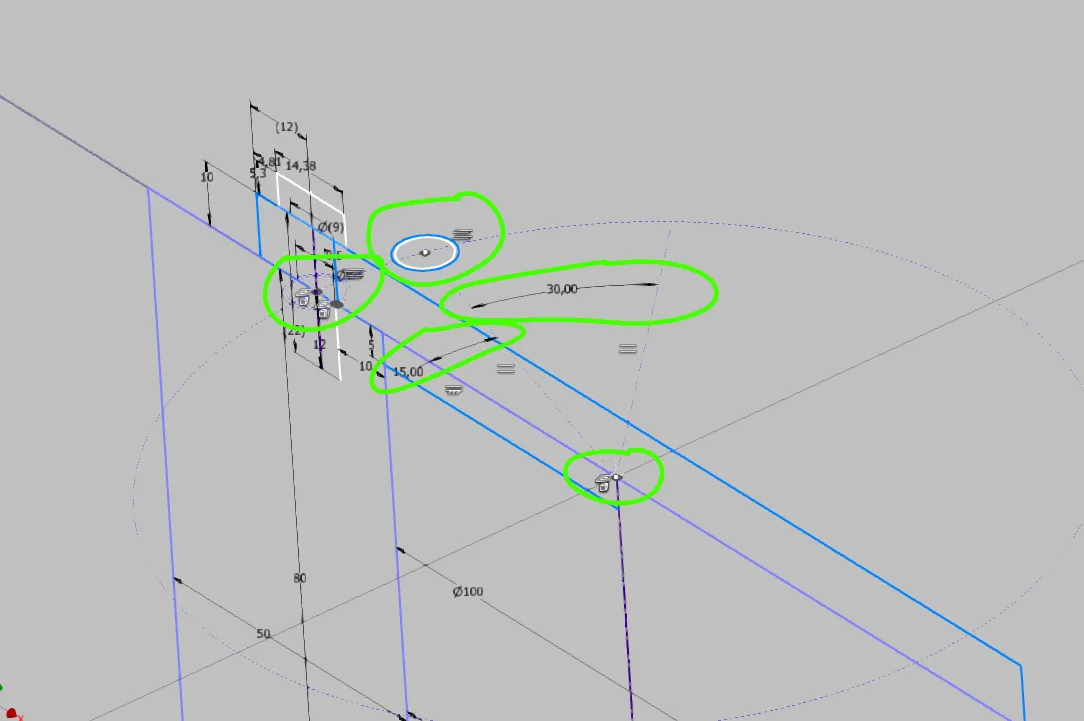
Next, the top view and the actual pattern are derived from the cross-section (Figure 1.3). The screw connection centerline, the thread line, the through hole line, if available countersinks and other lines, and the pattern center (= center of the bearing hole) are projected as points. Circles are drawn from the points of the screw connection itself that make the respective diameters visible. If a start angle plane was previously used, this is also projected and the circles can be "real" lines. In this example, the circles are construction circles. The hole circle is drawn as a construction circle from the pattern center to the screw connection center. For the start angle, an existing plane is projected or a dimensioned construction line is drawn, one further for the increment angle and possibly existing end angle. Since there is no start angle plane in the example, the circles for thread and through hole are drawn as circles equal to the projection at the end of the start angle line.
Create the derived patterns in the volume parts
The newly created sketches are included in the derivations (Creo: publish and copy geometries) for the individual parts as needed and the elements needed from them are projected into local sketches, as described in the tutorial on detailing. For the cover, only the top view is needed, as it only has a through hole and no countersink in the example.
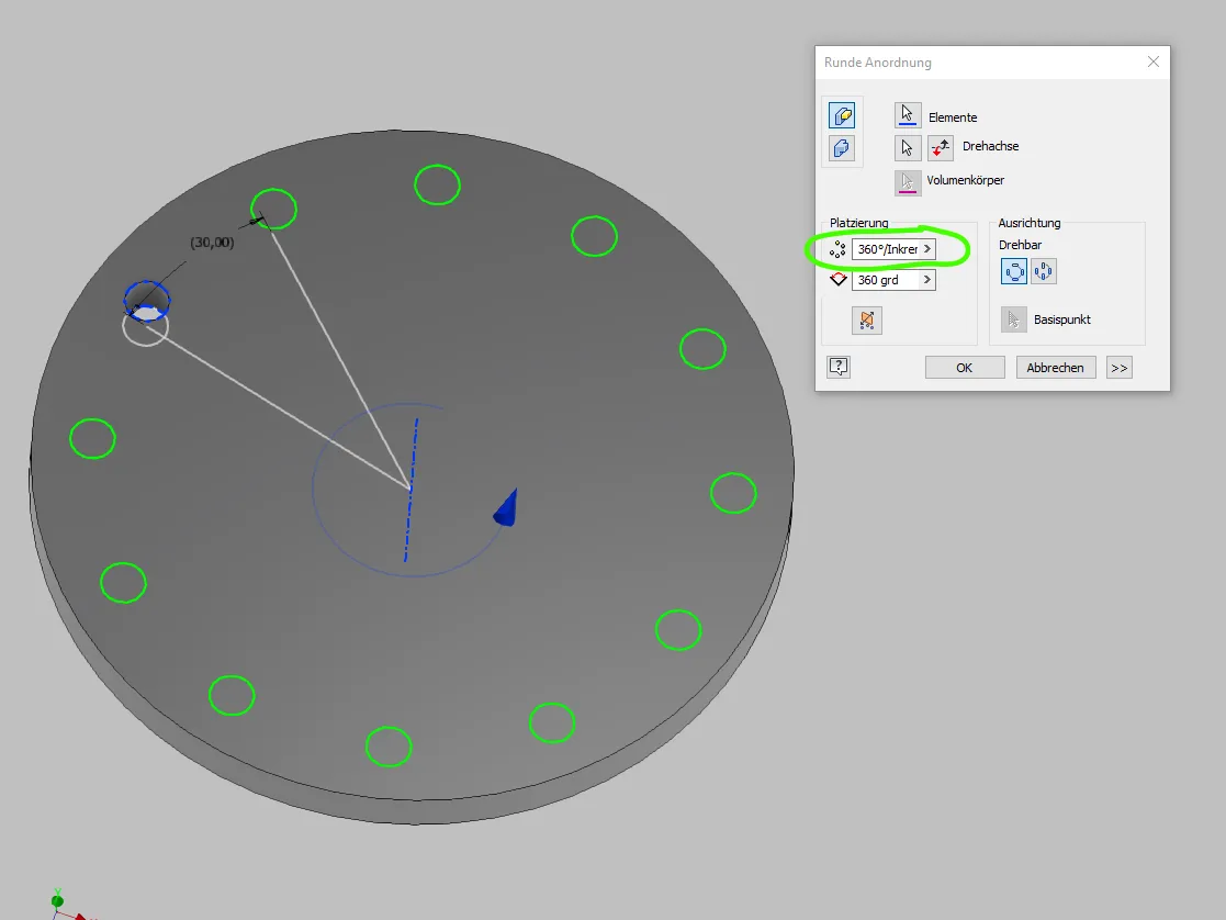
On the projected circle, an extrusion (Figure 1.5) is created, which is then patterned in the circle. The number of pattern elements is set as needed either to "360° / increment angle" or to "end angle / increment angle". If available, "end angle" is entered instead of 360° as the pattern area.
In the housing part, the same procedure is used in principle (Figure 1.6). Here, too, the top view is sufficient, but this time the thread circle is used instead of the through hole circle. To automate the thread, a UDF is recommended in Creo that references the thread circle and then sets its diameter and depth using an integrated "case" block. In Inventor it is a bit more complicated, here you need an iLogic script that is either kept externally or added to each model. My external script looks for dimensions whose name starts with "agt_" (automatic threads with depth) and identically named thread features to set the appropriate thread.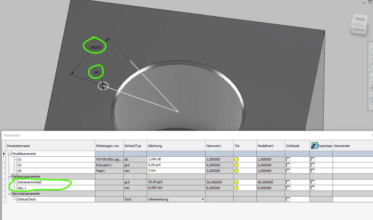
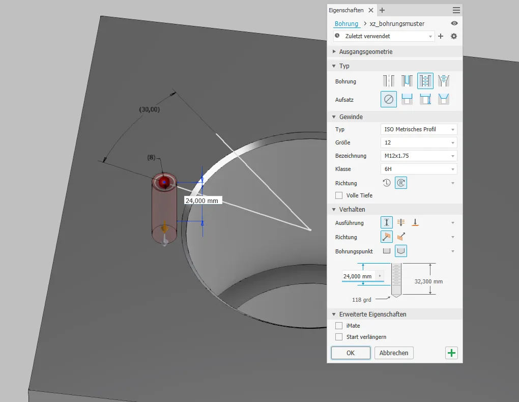
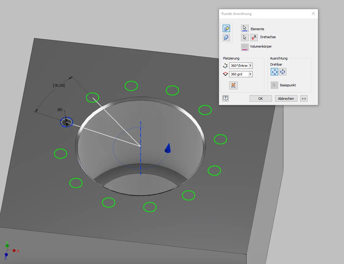
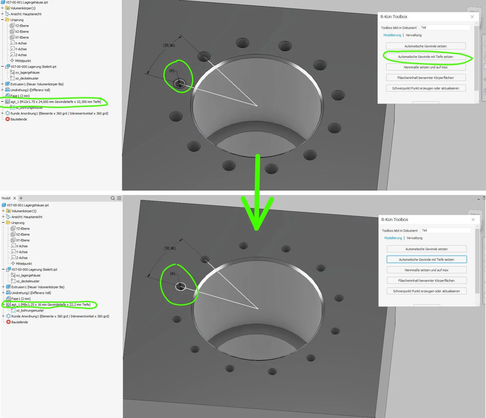
At the center of the projected circle, a threaded hole is created (Figure 1.7), which is then patterned in the circle (Figure 1.8). The number of pattern elements is set as needed either to "360° / increment angle" or to "end angle / increment angle". If available, "end angle" is entered instead of 360° as the pattern area. Since my script automatically sets diameter and depth, only the type needs to be set correctly.
Executing the script sets the thread properties according to the projection from the skeleton. (Figure 1.9)
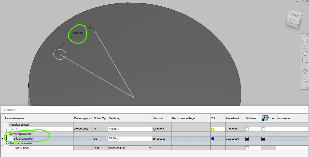
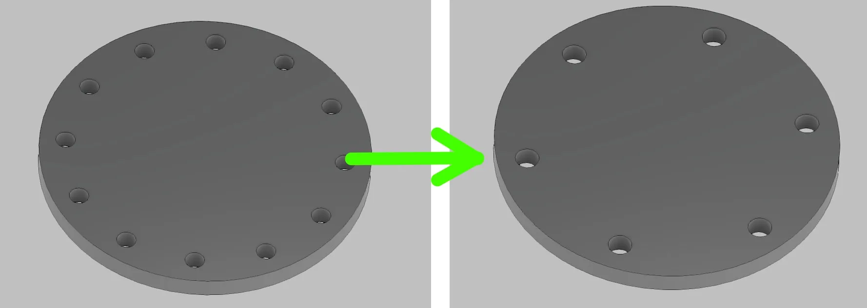
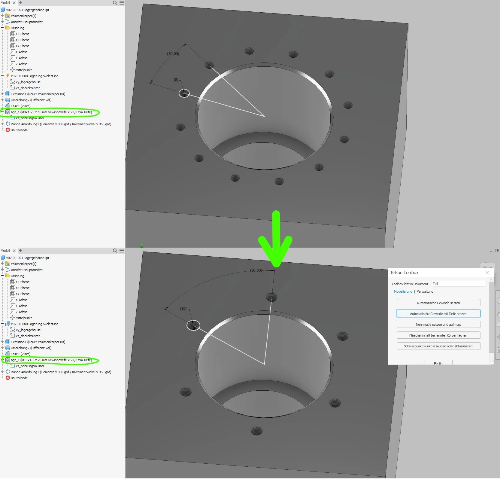
To adjust the screw connection, only minimal input is needed. In Figure 1.10, the increment angle is set from 30 to 60 degrees and the thread diameter from M8 to M10 to get fewer and larger holes. The distance to the through hole of 0.5 remains the same according to the standard.
The cover has correspondingly fewer and larger through holes after updating, the housing has fewer threads with a diameter of M10 instead of M8 after updating and executing the script, and larger depths for core hole and thread.
Conclusion
Automating circular patterns is a relatively small additional effort compared to conventional creation and offers great flexibility and error safety for future changes.
If you need more in-depth advice on CAD methods, please click on Contact.
You are also welcome to download the short presentation (sorry, only in German) on the topic. It may be used freely in unchanged form, including commercially, provided the source is acknowledged (license: CC BY-ND).
You can also download the model files in the finished state of this tutorial.
Click the links to copy to clipboard
This page: https://r-kon.eu/cad-runde-muster.php
The video: https://youtu.be/sGA5uz0yx6E (Youtube) / https://dai.ly/k5bfwfn5XneEJCD0mbQ (DailyMotion)