
Control rectangular patterns using a skeleton
How to create and control rectangular patterns, drilling patterns and screw connections for multiple parts in the skeleton
Links on the topic: The Video about skeleton-controlled rectangular patterns at Youtube or DailyMotion and the short presentation (sorry, only in German) as PDF.
The advantages of skeletton controlled round patterns and screw connections
Many connections between components are based on patterned elements. The input parameters of the patterns are usually very manageable: For the rectangular pattern, a line per pattern direction and one element in the top view are usually sufficient. In addition, a cross-section is usually required to determine the pattern elements. However, the synchronisation of these few values across the affected parts determines the assembly capability of the assembly. The manual transfer between the parts means unnecessary risk of error and avoidable drudgery.
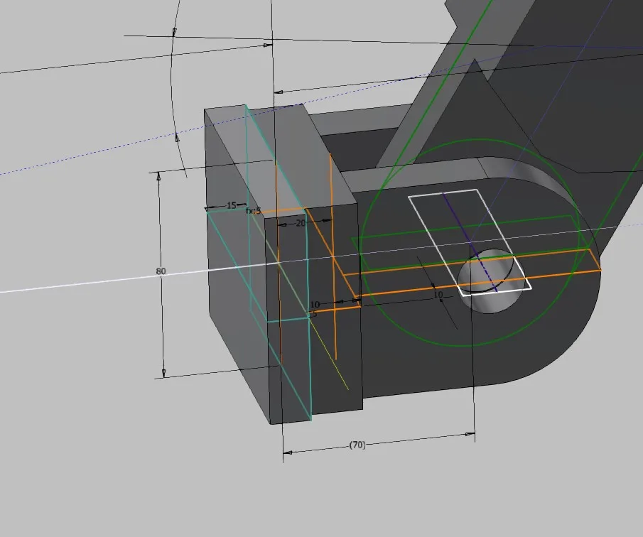
As an example, the end console of the already often shown articulated arm is shown in Figure 1.1. A connection part is to be screwed onto this console, for simplicity a plate as an example. The assembly is skeleton-controlled, the screw connection is to be made with cylinder screws.
Create rectangular patterns and screw connections in the sketch skeleton
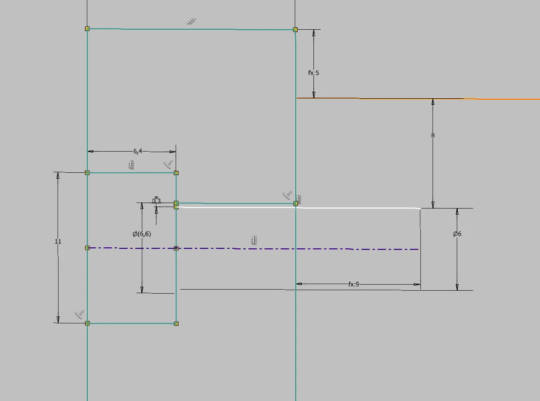
First, it must be determined which information is needed for the pattern elements and the pattern itself across multiple parts and how these are causally related. In the case of screw connections, as in this example, it makes sense to first draw a cross-section as shown in Figure 1.2. A half view is sufficient, the centerline is required. In cross-sections with countersinks or stepped holes, it may be useful to draw the cross-section on a plane rotated by the start angle. The relationship between thread, through hole, possibly countersink and their depths can be well represented in the cross-section, in addition, the suitable edge distance for the hole circle diameter can be indirectly chosen with the diameters of the holes and screw heads. Also possibly to be considered assembly space, for example for sockets should be drawn and referenced in this cross-sectional view.
The center of the screw connection results from a necessary distance of the thread from the edge of the plate (dimension 8) and the screw diameter. The through hole is dimensioned relative to the thread line and made visible by a reference dimension (9). This ensures that the through hole is always larger than the thread, even if the user forgets to set the correct diameter for the thread size. If the through hole were directly dimensioned, an unmountable part could be manufactured due to this fluke error.
The thread depth is automatically calculated according to the well-known rule of thumb 1.5*d. This results in the minimum required screw length, which can be read directly at reference dimension 22. The standard depths of threads are chosen for common sizes so that here always fits the next larger screw length.
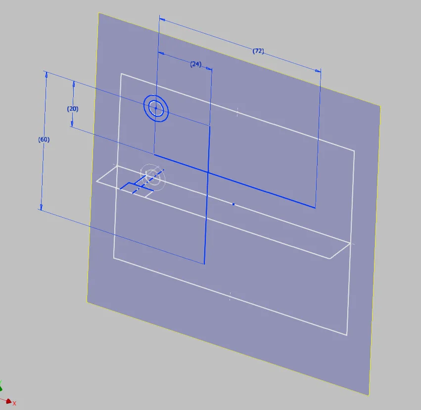
Next, the top view and the actual pattern are derived from the cross-section (Figure 1.3). The screw connection centerline, the thread line, the through hole line and the countersink line are projected as points. Circles are drawn from the points of the screw connection itself, which make the respective diameters visible. In this example, the circles are construction circles, since the cross-section is not defined in the pattern starting point. The first pattern member is drawn into a corner with equalized "real" lines and the yet undefined vertical distance is dimensioned. For both pattern directions (vertical and horizontal), one line each is drawn. One end of the line is aligned to the first pattern element, the other in this case with an equalized dimension to equal edge distance, i.e. symmetrically. In Inventor, the lines must not be connected at a corner, as otherwise the curve pattern generated later would go around the corner. Therefore, it is advisable to place the intersection of the lines so that the distance of one line from the end of the other indicates the increment. The dimension should be defined sensibly with an equation on "length / number". If the number of elements in one direction should be immutable, the other line can be made coincident to the center of the corresponding pattern line. If only one direction is desired for the pattern, the second line is omitted and a point or circle on the pattern line can be used to indicate the increment.
Create the derived patterns in the volume parts
The newly created sketches are included in the derivations (Creo: publish and copy geometries) for the individual parts as needed, and the elements needed from them are projected into local sketches, as described in the tutorial on detailing. For the connection part, in this example, in addition to the top view, the cross-section is also needed to transfer the depth of the countersink.
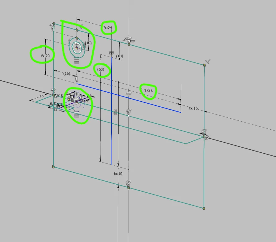
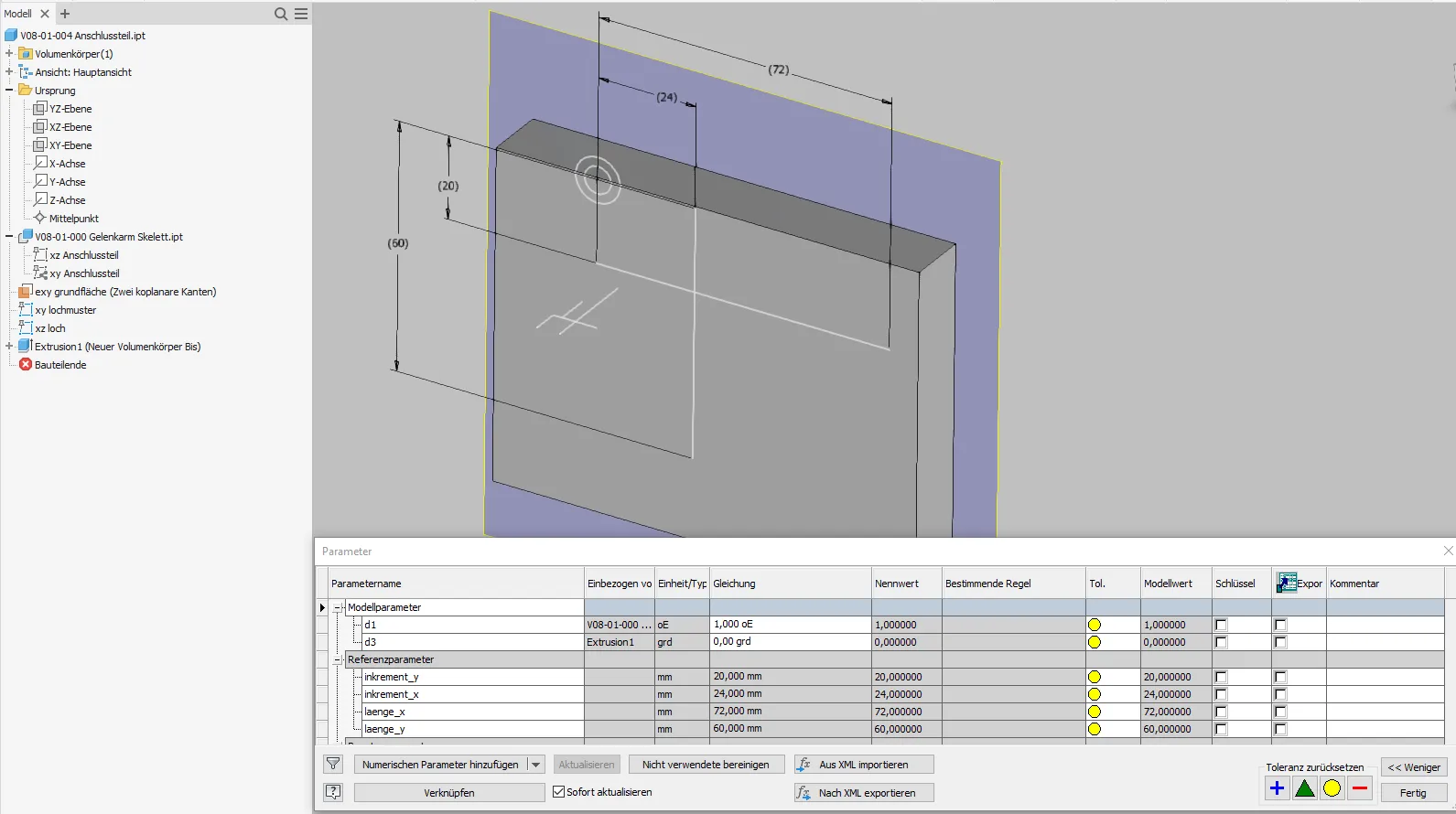
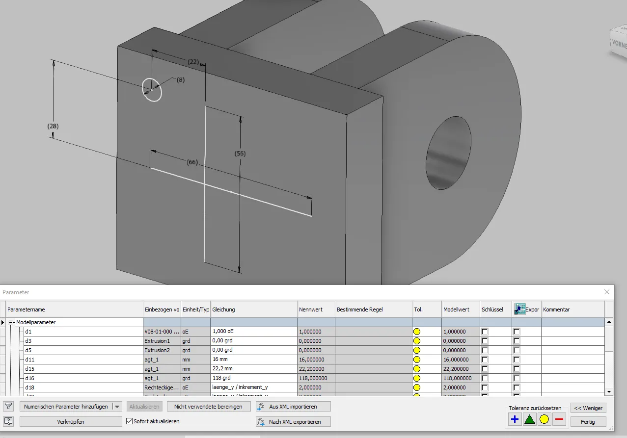
As can be seen in Figure 1.4, the circles for the through hole and the countersink and the two lines for the pattern directions are projected. Reference dimensions are created for the increments and total lengths, which are sensibly named via the parameter list (Figure 1.5). If several patterns are present, a naming system with pattern names or numbering is recommended; in this example, "increment" and "length" each with directional indication are sufficient. The dimensions are only required for directions in which the number of pattern elements is to be variable.
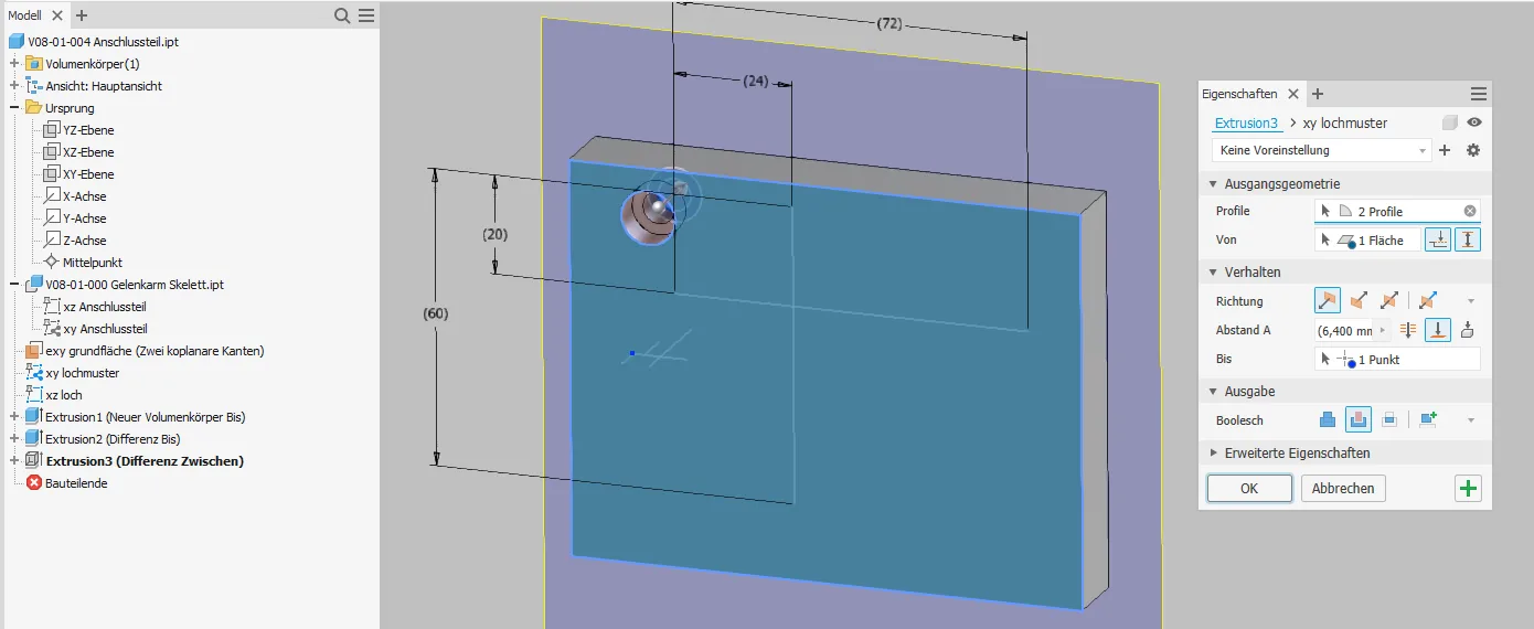
Since you can now freely choose both the start and end plane of an extrusion in Inventor just like in Creo, the countersink can be easily created as an extrusion from the top view sketch from the surface to the corner point in the countersink cross-section as shown in Figure 1.6. The through hole is simply extruded from surface to surface.
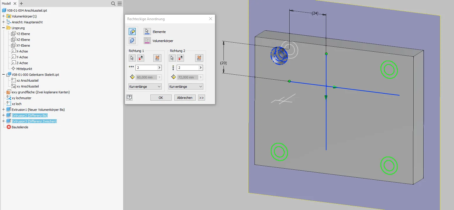
The created extrusions are patterned together. For each direction with a fixed number of elements, it is sufficient to select a pattern line as shown in Figure 1.7 and set the element distribution to "curve length".
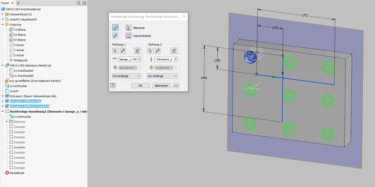
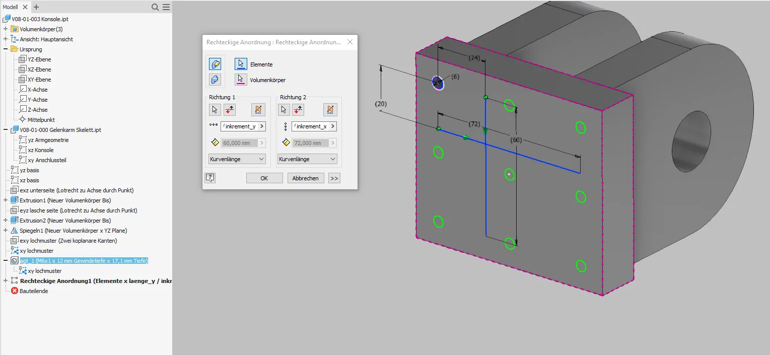
If the number of elements is to be variable, the number of elements for the respective direction is also specified with "length / increment" as shown in Figure 1.8.
The same procedure is applied in the console of the arm (Figure 1.9). Here, too, the top view is sufficient, but this time the thread circle is used instead of the through hole circle. Again, named reference dimensions are created for increments and lengths. To automate the thread, a UDF that references the thread circle and then sets its diameter and depth via an integrated "case" block is recommended in Creo. In Inventor it is a bit more complicated, here you need an iLogic script that is either kept externally or added to each model. My external script searches for dimensions whose name starts with "agt_" (automatic threads with depth) and identically named thread features to set the appropriate thread.
The threaded hole is placed on the projected point or circle in the pattern corner of the top view and then patterned according to Figure 1.10. The dimensions of the thread are set by a script according to the diameter circle in the projection.
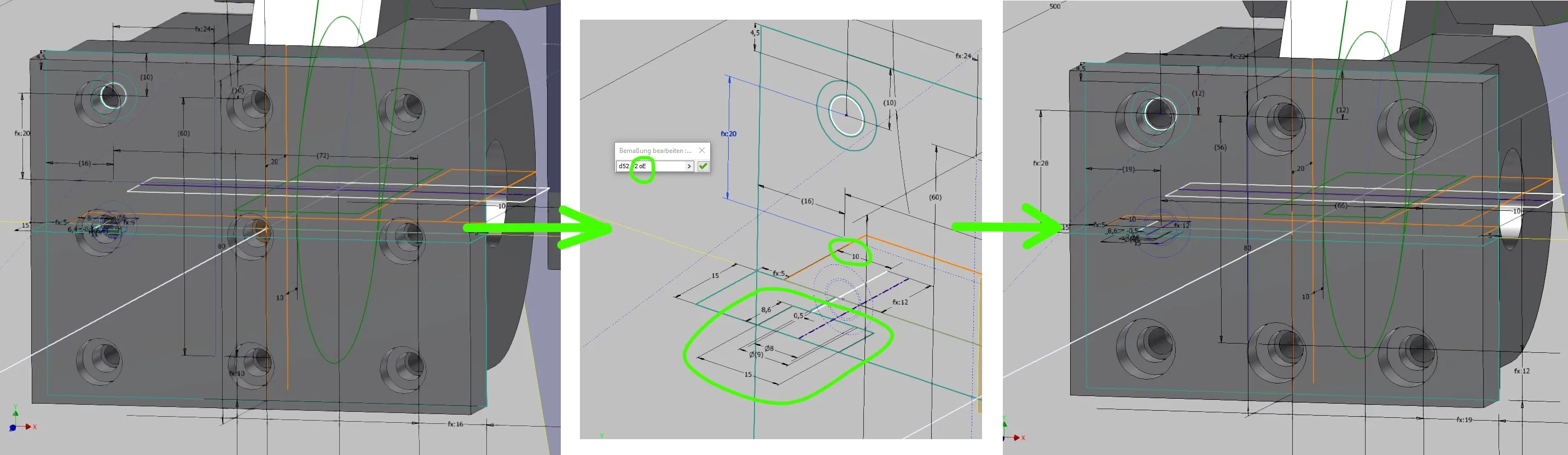
To adjust the screw connection, only minimal input is required. In Figure 1.11, the number of vertical pattern elements is set from 3 to 2, the horizontal distance to the plate edge is increased from 8 to 10, and the screw size is changed from M6 to M8, which affects the countersink, the through hole and the thread.
After the update, the console and connection part have matching hole patterns in the correct size without manual intervention.
Conclusion
Automating rectangular patterns is a relatively small additional effort compared to conventional creation and offers great flexibility and error safety for future changes.
If you need more in-depth advice on CAD methods, please click on Contact.
You are also welcome to download the short presentation (sorry, only in German) on the topic. It may be used freely in unchanged form, including commercially, provided the source is acknowledged (license: CC BY-ND).
You can also download the model files in the finished state of this tutorial.
Click the links to copy to clipboard
This page: https://r-kon.eu/cad-rechteckmuster.php
The video: https://youtu.be/Hz2gQtl79q4 (Youtube) / https://dai.ly/k2IpNNJFD7r6LCD0Lhc (DailyMotion)