Adding parts to skeleton-controlled assemblies
Expand assembly skeleton, create additional parts and adjust dependencies
Links on the topic: The Video about creating a skeleton-controlled assembly at Youtube or DailyMotion and the short presentation (sorry, only in German) as PDF.
Skeleton-controlled assemblies: Flexible despite demanding structure
In this tutorial I will show you how to add additional parts to skeleton-controlled assemblies and how to "reattach" design-related references from the previous references to a new part, both in the skeleton and in the assembly. On the way from the draft to the finished design, this becomes a routine process that can be easily and quickly completed with a structured approach. This example also shows that skeleton-controlled assemblies are not fundamentally inflexible, but can also be expanded and rebuilt with reasonable effort.
Incorporate new parts into the skeleton
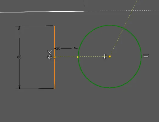
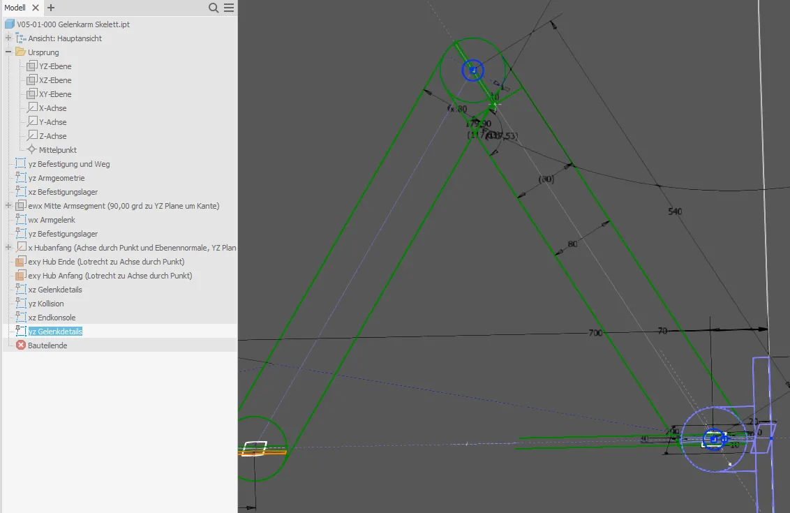
The articulated arm, which has already been shown several times, is to have a bracket at its end to which something can be bolted. The procedure is very similar to the initial design of an assembly, only now the careful consideration of the design logic and functional dependencies becomes even more important. Where necessary due to mutual dependencies, the new part is represented in existing sketches and the dimensions and geometric conditions are adjusted accordingly or "reattached". In this case, this is the sketch "Arm geometry" marked in Figure 1.1, because so far the pivot point of the arm end has been linked to the stroke, where the screwing surface of the bracket is to be located in the future.
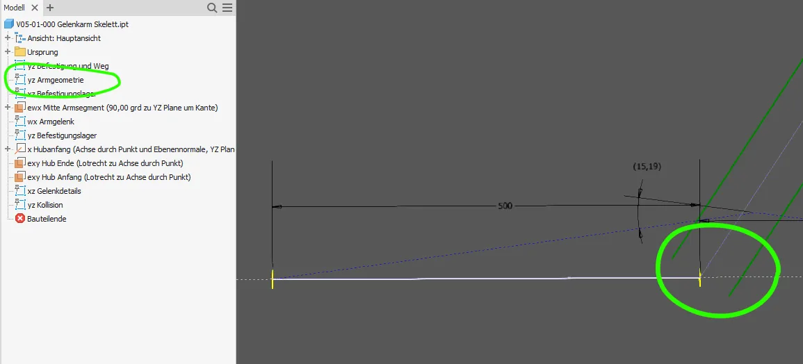
It is usually advisable to make additional sketches for new parts so that the scope of the sketches remains manageable. If you want to install a new part between two other existing ones and on the one hand the new part should be based on the properties of the existing ones but on the other hand should also change their properties in return, all mutually relevant elements must be put together in one sketch. An illustrative example is a thrust washer added later in a joint connection, whose thickness "pushes away" the adjacent parts, but whose diameter must be based on the adjacent parts. In the assembly shown here, the bracket is installed between the end of the arm and the environment symbolized by the stroke. For this purpose, the coincident conditions shown in Figure 1.2, which connect the stroke line with the center lines of the arm for both end positions, must be deleted.
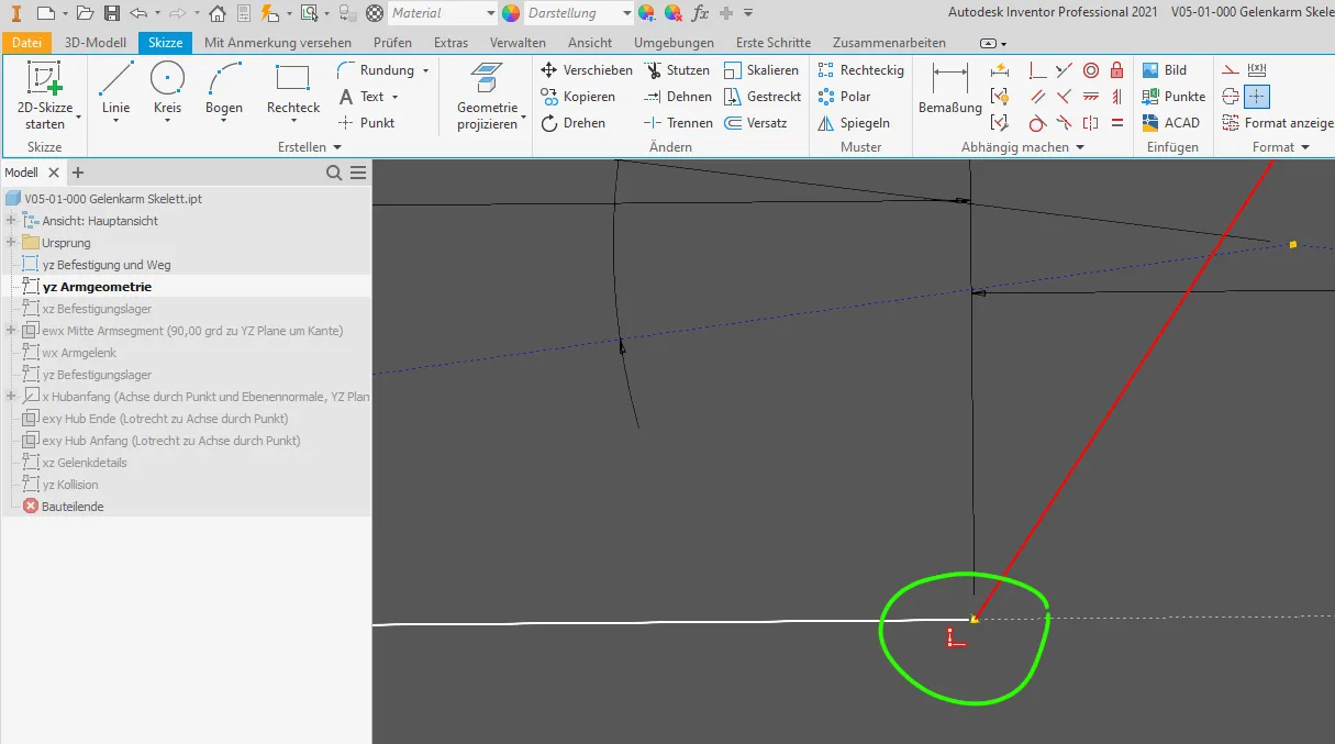
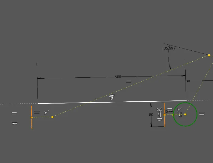
As in Figure 1.3, I always pull the line ends a little away so that they are clearly visible and do not accidentally snap back together when working further.
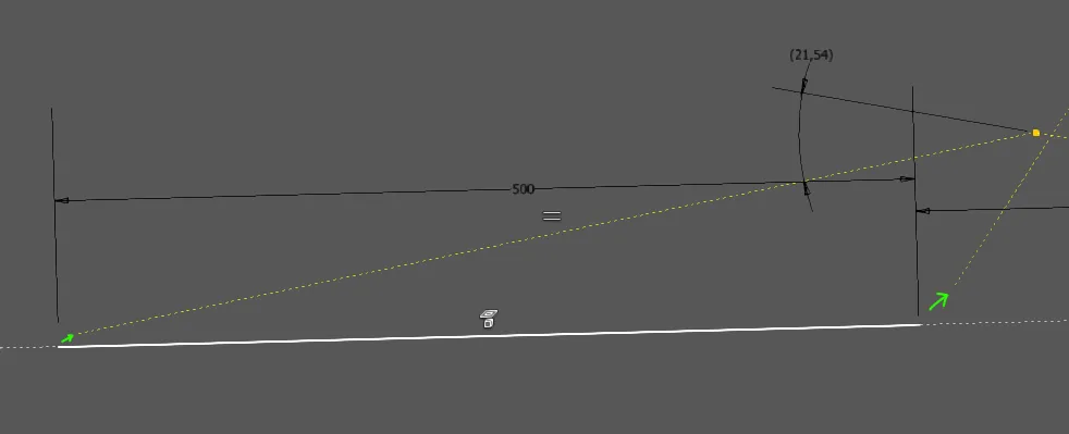
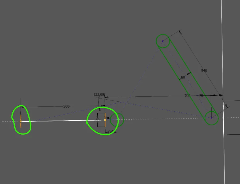
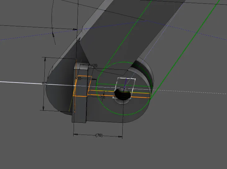
Next, at the end of the center line for the arm segment at the beginning of the stroke, I only draw the most necessary elements: the circle for the arm rounding (equated with the circle already present at the other end of the arm segment) and a line for the screwing surface, which I keep at a distance from the arm end with a central construction line and a point (Figure 1.4). The redesigned arm end is still movable, for better clarity I have moved it slightly below the stroke line. In Figure 1.5, it can be seen that only the equated center line with the perpendicular for the contact surface is drawn on the center line for the arm segment at the end of the stroke. More is not needed here to define the bracket.
The midpoints of the vertical bracket lines or the end points of the horizontal construction lines are now reattached to the two end points of the stroke line with coincident dependencies, where the construction lines were in the middle of the arm segments before, as shown in Figure 1.6.
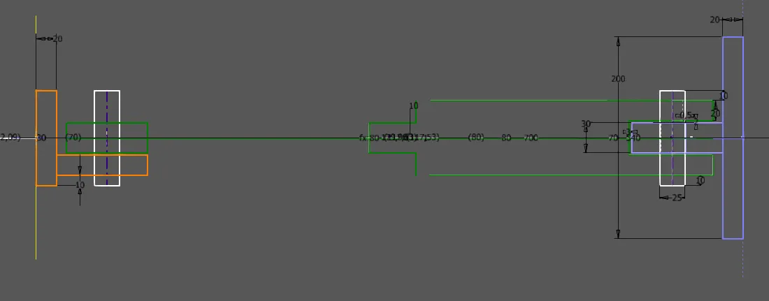
For properties of the new part that do not mutually influence the existing geometry, new sketches are created as when adding details (Figure 1.7). If the environment is to be influenced by this, the new sketch must be inserted in the tree in the order where it belongs according to the design idea. The sketches of the adjacent parts to be influenced must follow the new sketch so that they can refer to it. In this case, nothing depends on the details of the new bracket drawn in the top view, so the sketch can be at the end as in Figure 1.7. I take over the dimensions of the bolts and tabs as well as the end of the arm segment from the projected lines of the previous sketches so that I can use identical parts. With this top view, the bracket is fully defined, the result in Figure 1.8.

The sketches needed for the bracket have to be selected and a new part with derivation is created using the create component function and inserted into the specified assembly (Figure 1.9).
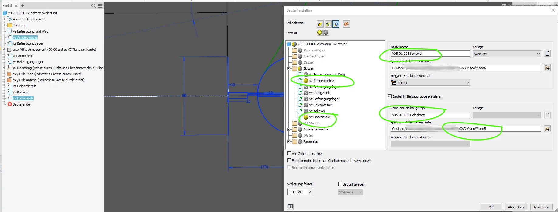
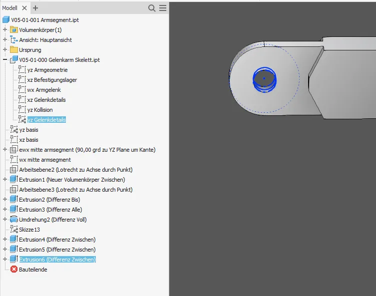
On this occasion, I also add the hole for the second arm segment end in an additional sketch (Figure 1.10). The diameter is equated with the hole already drawn with play in the mounting bearing so that the bolt can be identical.
Create volume part and adapt assembly
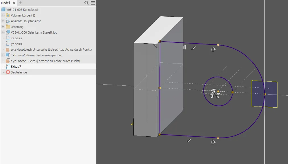
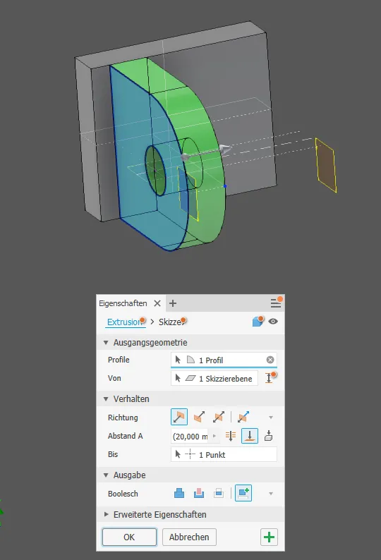
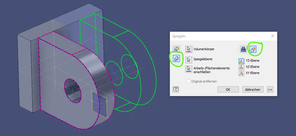
In the part, the volumes are created as described in "Building a skeleton-controlled assembly". Since the bracket is to be a welded part, I create the tabs and the base plate as independent volumes, so the bracket is a "multibody-part". If offset planes are needed for the extrusions, they should be created on lines and end points of the base sketch to be stable (Figure 2.1). The side view in Figure 2.2 is derived from the projected points in the top view. The extrusions are drawn "up to point" or "up to plane" to be controlled by the skeleton (Figure 2.3). I consider the mirroring of the tab as a new volume in Figure 2.4 to be an acceptable, because sufficiently stable, simplification.

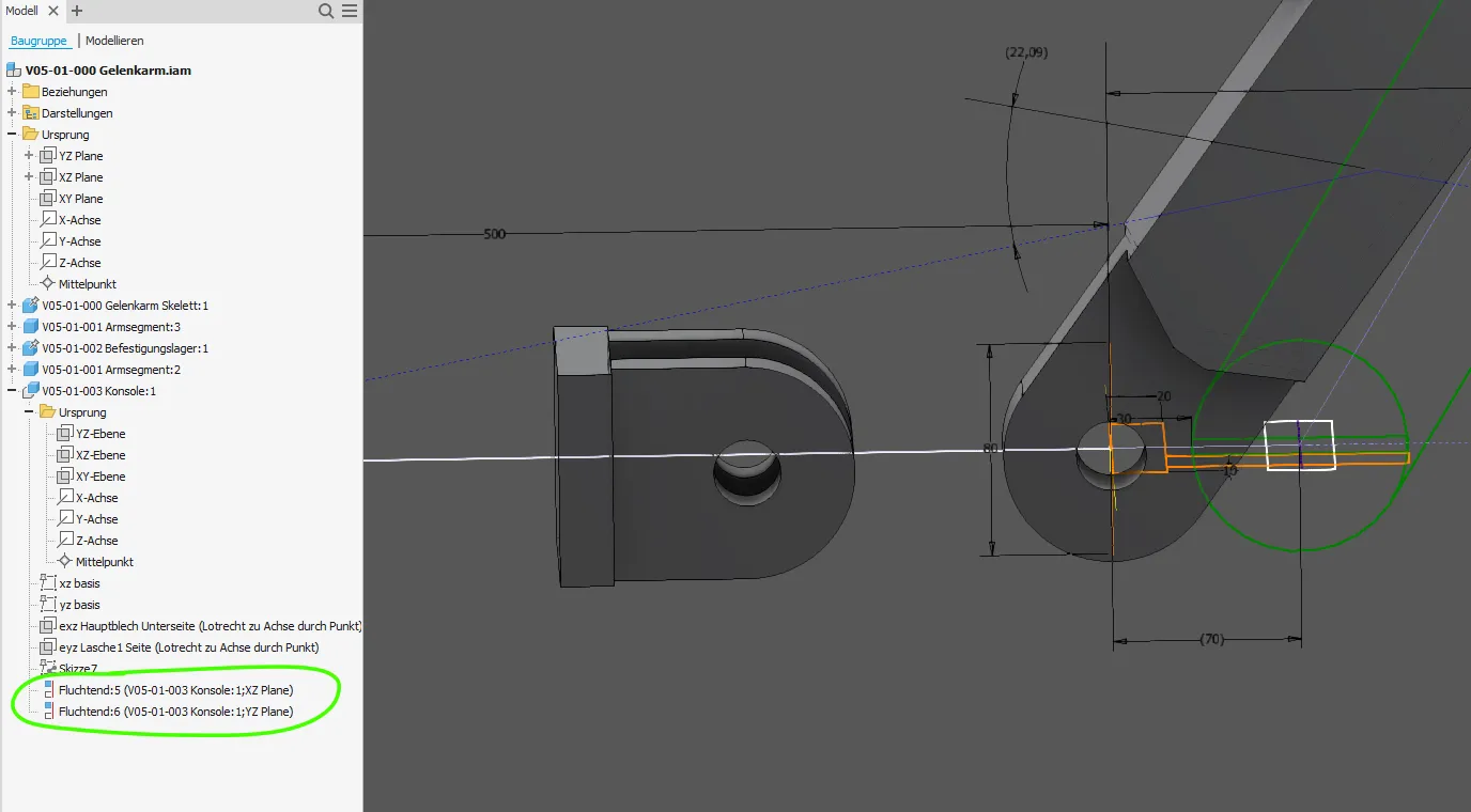
Now the new bracket can be positioned correctly in the assembly. In Figure 2.5 you can still see the initial state: The bracket was automatically grounded where it is shown in the skeleton, and the second arm segment is still defined with its pivot axis on the end of the stroke. In Figure 2.6, the grounding is released and instead the bracket is placed on the XZ and YZ plane to idealize the guided load. In the stroke direction, it is freely movable.
The relationships "stroke min", "stroke max" and "stroke limits" can now be related to the screwing surface of the bracket instead of the arm segment axis. The direction (opposite / same direction) may need to be switched. With the "stroke limits" relationship, it can happen again that the positive direction is wrong. The positive direction in relationships between two surfaces / planes in Inventor is based on reference 1, so you may have to take the work plane from the skeleton as the first reference as in Figure 2.7. Normally, it would be clearer if reference 1 were always the part to be installed.
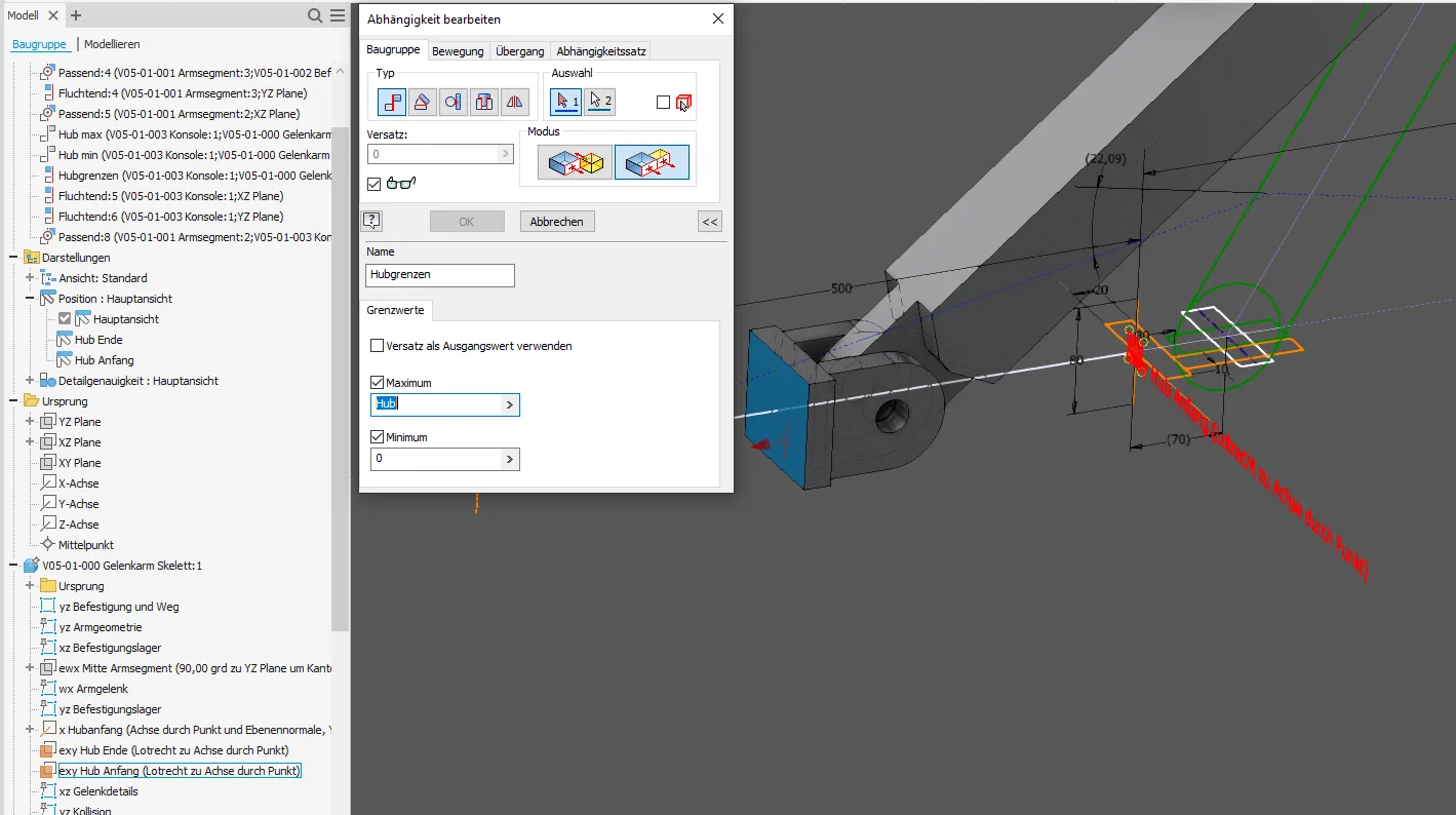
The changed relationships are supplemented by a non-aligned axis relationship between the pivot axes or holes at the end of the segment and the bracket tab to represent the bolt connection. The dependencies are now complete, the result is shown in Figure 2.8. For the sake of clarity, I like to move the conditions relevant for the movement to the very top.

The assembly is now consistent again and all movement states and drawing views are also functional with the added part.
Conclusion
As this example shows, subsequent changes to movable and fully skeleton-controlled assemblies are easily possible. The relationships defined in the design stage can be changed and expanded during the detailing process as the scope of the assembly grows.
If you need more in-depth advice on CAD methods, please click on Contact.
You are also welcome to download the short presentation (sorry, only in German) on the topic. It may be used freely in unchanged form, including commercially, provided the source is acknowledged (license: CC BY-ND).
You can also download the model files in the finished state of this tutorial.
Click the links to copy to clipboard
This page: https://r-kon.eu/cad-teile-hinzufuegen.php
The video: https://youtu.be/ywhr3qafjAI (Youtube) / https://dai.ly/k2eN3ygAnPCQp4CzcPm (DailyMotion)
