
Foresighted model design
Preparatory considerations for productive modeling and reusability of models
Links on the topic: The Video about foresighted model design at Youtube or DailyMotion and the short presentation (sorry, only in German) as PDF.
Model structure: What is actually best?
There are countless answers to this question, which are as varied as the CAD models and their purposes. Answering them is important, but often not easy, as each approach has its advantages and disadvantages.
To make matters worse, many designers learn in CAD training courses how to operate the CAD system and how to get blocks into the space and lines onto the drawing, but not which of the many possible ways to the finished model is most suitable for the application. This is often only possible with years of experience, at least for people who are able to develop and try out new methods at work.
Systematic preliminary considerations, which should take place before the actual modeling, help to make the search for the optimal individual modeling strategy easier.
The topic is highly relevant in my seminars and I would like to give you an overview of which modeling strategies are suitable for what and how you can proceed with the selection.
Approach
When it comes to finding the most suitable procedure for constructing assemblies or components, the following basic procedure is recommended:
- Clarify and, if necessary, document what the modeling objective is, i.e. what properties models and drawings should have
- Search for and, if necessary, test methods that fulfill these goals as well as possible
- Once the methods have been successfully selected, agree or update the team's conventions accordingly
Examples
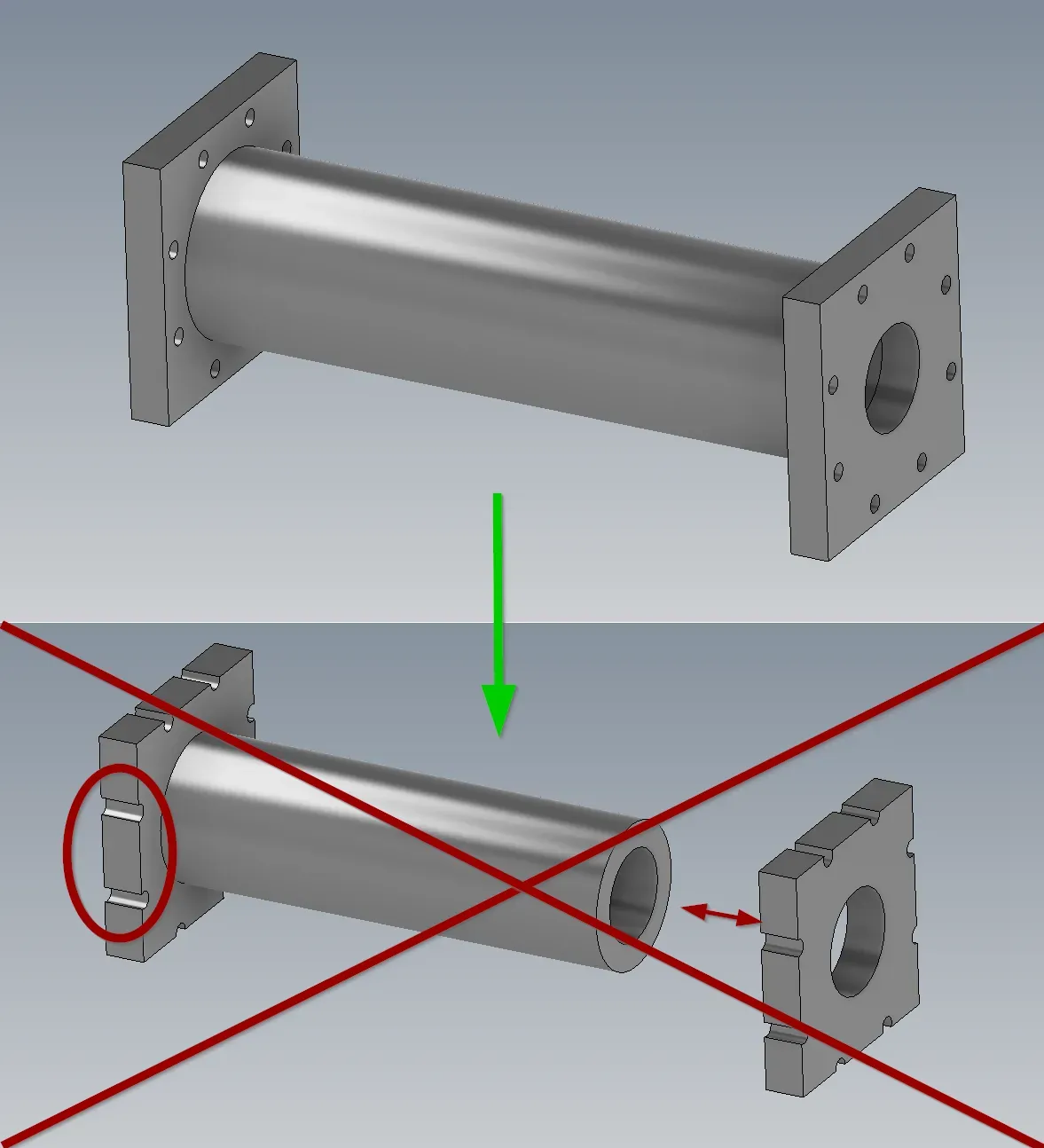
The pipe with flanges shown in Figure 1.1 is intended to connect two adjacent bodies. It is functionally defined mainly by a pipe diameter, a wall thickness and the distance between the connecting surfaces of the flanges. These values can change depending on the use of the model. My expectation, i.e. the modeling goal, is that when these functional parameters are changed, the model retains a coherent state, meaning that the mounting holes are in a plausible position and the connection between flanges and pipe is correct. If this part is modeled clumsily, the following happens when the parameters mentioned are changed:
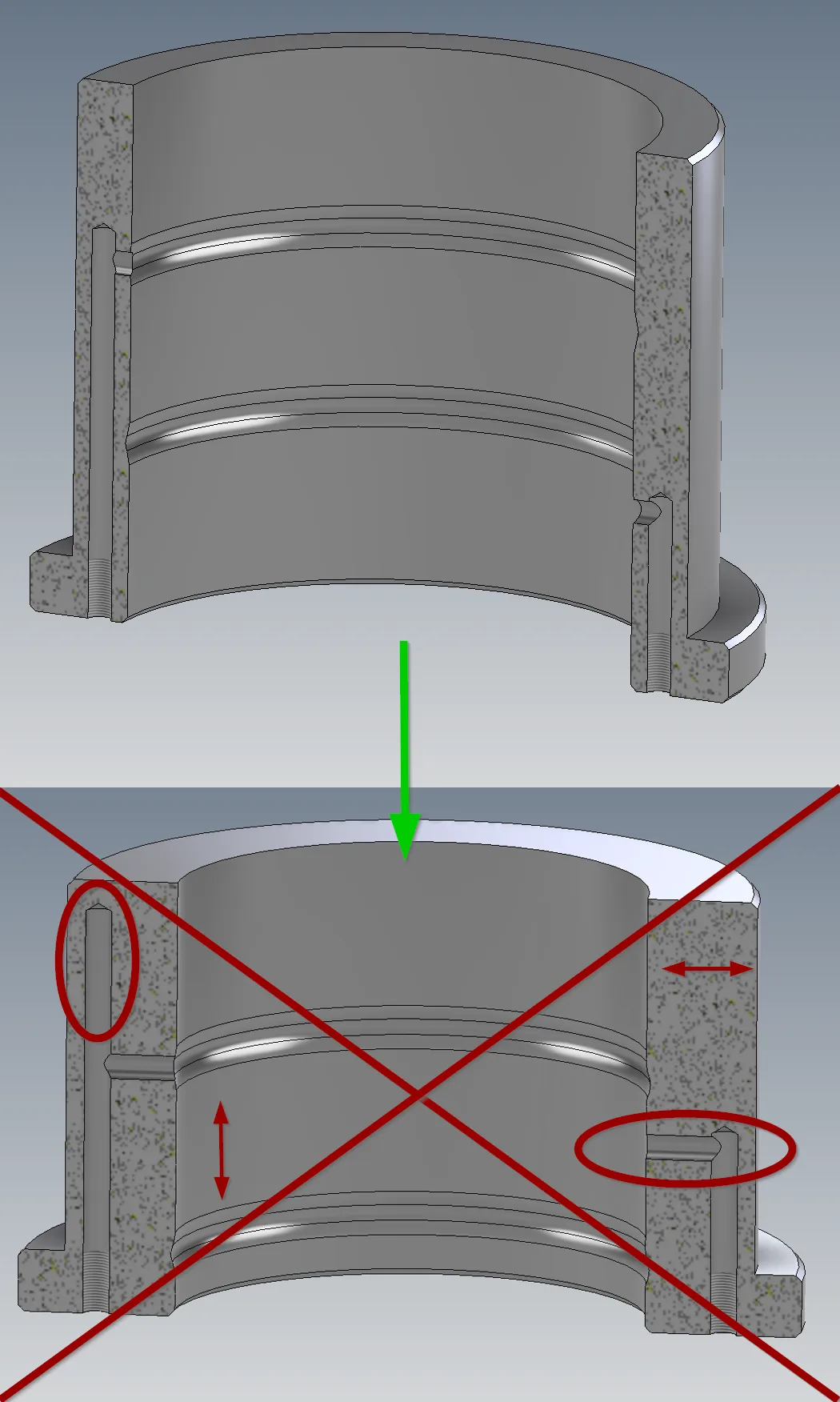
The model in Figure 1.2 also behaves implausibly. The internal ring grooves should be supplied with pressure oil through holes from the front. According to the standard, the grooves should be at about 1/3 and 2/3 of the seat height. The sleeve should be available in different diameters and heights for different shaft sizes, the wall thickness and the collar are always similar in proportion to the diameter. My expectation would be that I can change the inner diameter and the seat height and that the grooves are in the right place and the connection holes meet the grooves. However, if the inner diameter and height are not modeled properly, the result can be as shown in the picture.
Approach
It is therefore normally desirable for models to behave in accordance with functional expectations. The expectations can be completely different or even contradictory depending on the application, as they depend on what is to happen to the model after it has been created.
- Clarify existing input data and required output data
- Understand the design logic of the model to be created
- Consider expected changes
- Determine suitable model structure
- Plan stable references
Possible detailed questions arising from this workflow are, for example:
- What are the characteristic properties of the component? Input and output variables, catalog values, gradations, ...
- What changes are to be expected after the initial creation (also on copies!)? Which values are fixed, which are variable?
- Which data of the edited model is relevant for other models? How are they transferred? Do interfaces have to be specified?
- Are input parameters (for forms, scripts or from tables) required?
- What is the functional logic of the component and what should be mapped?
For very basic considerations, it is a good idea to visualize the decision-making process. I have created decision diagrams for some common cases, which can be downloaded further down on this page.
With the simple preliminary considerations in Figure 2.1, the flange pipe from the previous example can be designed more plausibly in line with expectations. If the interface dimension, the distance between the outer surfaces, is entered in an additional sketch, the flange size depends on the hole pattern and the hole pattern is given its size depending on the sketches of the other bodies, changes in length and diameter are no longer a problem. (Figure 2.2)
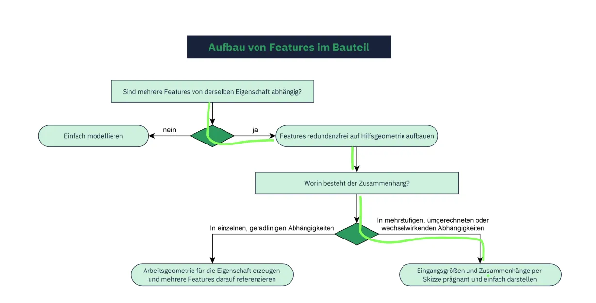
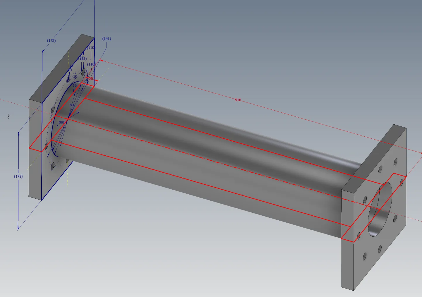
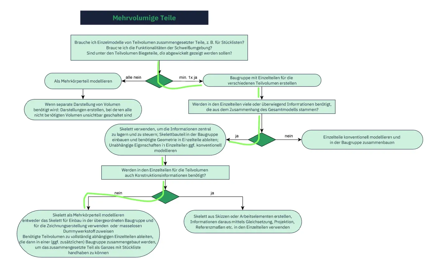
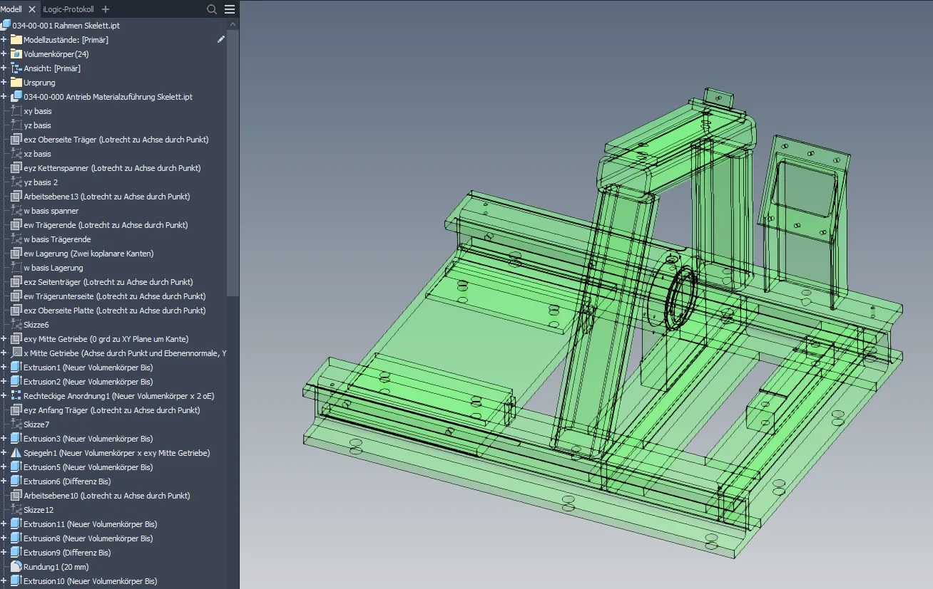
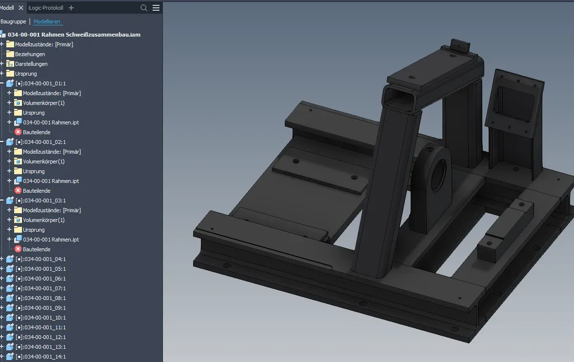
Figure 2.3 shows an example of the considerations that can be made for a multi-body part such as a welded part. This also shows that the structure of the welded part model can differ fundamentally depending on the use of the model. In the frame in Figure 2.4 and Figure 2.5, all geometry in the skeleton is defined as a solid, then the solids of all types of individual parts are derived into one component each and these components are then assembled into an assembly. In this case, the machining geometries are also derived, but it would also be possible with model states to derive the state before machining and use the skeleton for the machining drawing.
Of course, much more complex considerations can be made for assemblies.
In general, it can be said that the following procedure is usually favorable for the changeability of models:
- First sketch or model the input values and unchangeable properties
- Build all further features with references that are as stable as possible following the functional logic
- Establish relationships between features using parametric equations or iLogic
Conclusion
Such flowcharts are a way of clearly presenting the conventions agreed in a team. This means that every team member, even if they are new to the team, will arrive at roughly the same result. Of course, it requires a little extra effort at the beginning to plan the procedure in this way, but this can save a lot of work when the models are used or changed.
You can download the flowcharts (sorry, only in German) for the conceptual design of components and assemblies in CAD and use them freely in unmodified form, even commercially, provided you cite the source (license: CC BY-ND).
- Clarify and, if necessary, document what the modeling objective is, i.e. what properties models and drawings should have
- Search for and, if necessary, test methods that fulfill these goals as well as possible
- Once the methods have been successfully selected, agree or update the team's conventions accordingly
If you need more in-depth advice on CAD methods, please click on Contact.
You are also welcome to download the short presentation (sorry, only in German) on the topic. It may be used freely in unchanged form, including commercially, provided the source is acknowledged (license: CC BY-ND).
You can also download the model files in the finished state of this tutorial.
Click the links to copy to clipboard
This page: https://r-kon.eu/cad-vorausschauender-modellaufbau.php
The video: https://youtu.be/r0W-TDQxjMc (Youtube) / https://dai.ly/k4W8URfYm5x3KtzDk7C (DailyMotion)