
Sketch blocks
Advantages and disadvantages of sketch blocks and their use in sketch skeletons
Links on the topic: The Video about sketch blocks in sketch skeleton models at Youtube or DailyMotion and the short presentation (sorry, only in German) as PDF.
Sketch blocks in sketch skeleton models
Sketch blocks are a feature that Autodesk probably took from the AutoCAD world: a sketchpad groups a number of sketch elements into a block, which can then be manipulated and reproduced as a whole without any changes. This feature is intended to save us work. Unfortunately, there are only limited uses for sketch blocks in connection with sketch skeletons, but in principle it is possible to use them sensibly in this context too.
Example: I-beam
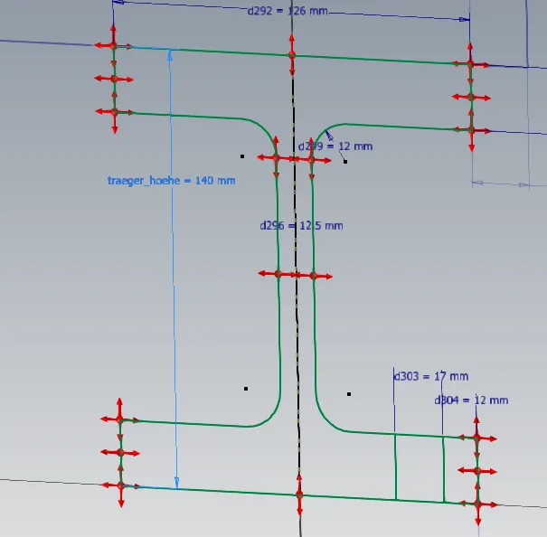
A small example illustrates this: A cross-sectional representation of an I-beam contains a number of constraints and dimensions on a group of sketch elements. The nature of this cross section is specified by a standard.
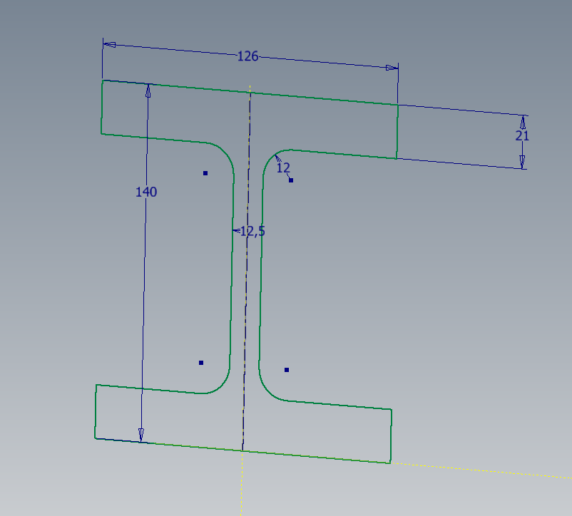
The interfaces on this beam should be screw connections on the lower flange (only indicated in the picture) and a welded sheet metal on the upper flange. If this beam is the only one of its kind, just draw it like that. In this example, the beam should be part of a frame in which several copies of the beam are installed in parallel.
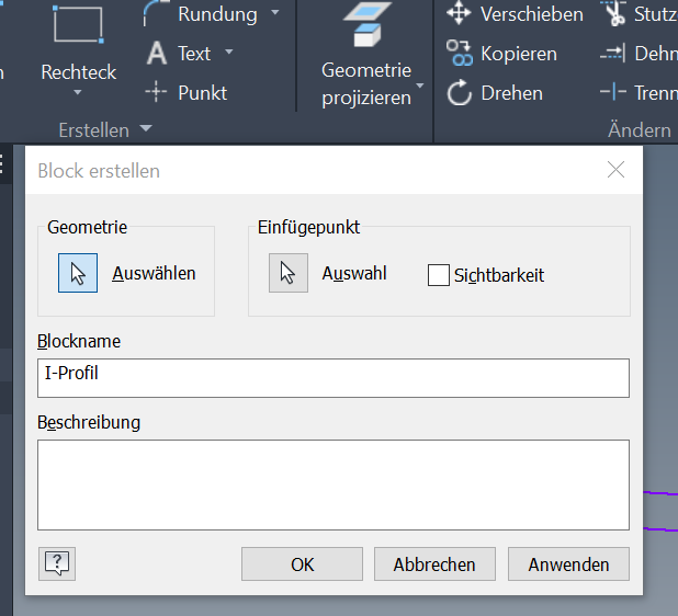
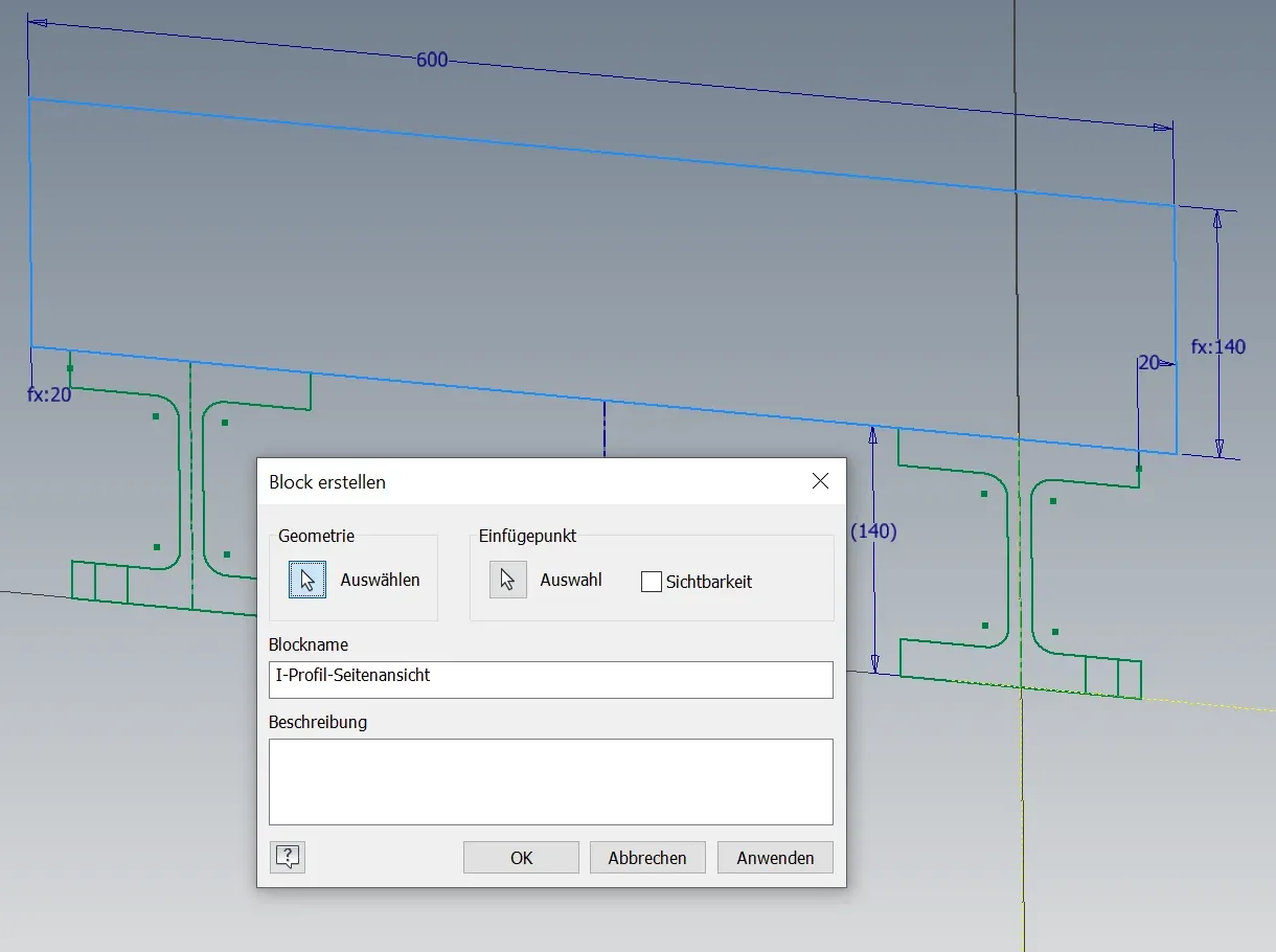
To represent this, one can combine the elements that make up the beam profile into a sketch block by selecting them and using the Create Block function in the Create ribbon group. In the following dialog you assign a name and an insertion point at which the block is "touched" from the outside. It can happen that the new block has no geometric restrictions connecting it with its surroundings and you have to set them again.
Within the block, the elements no longer have any relation to their surroundings because there is no way to geometrically reference the surroundings from within the block.
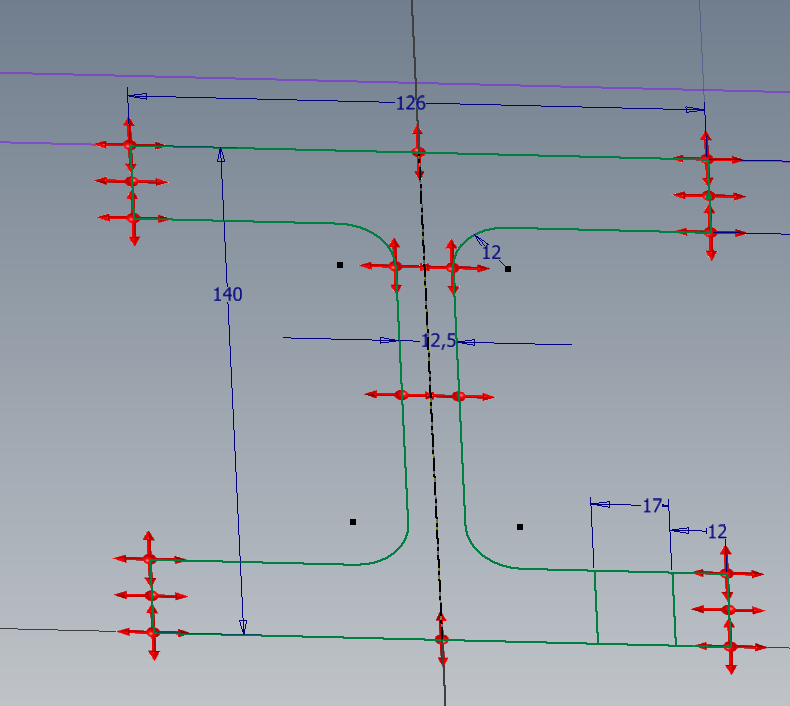
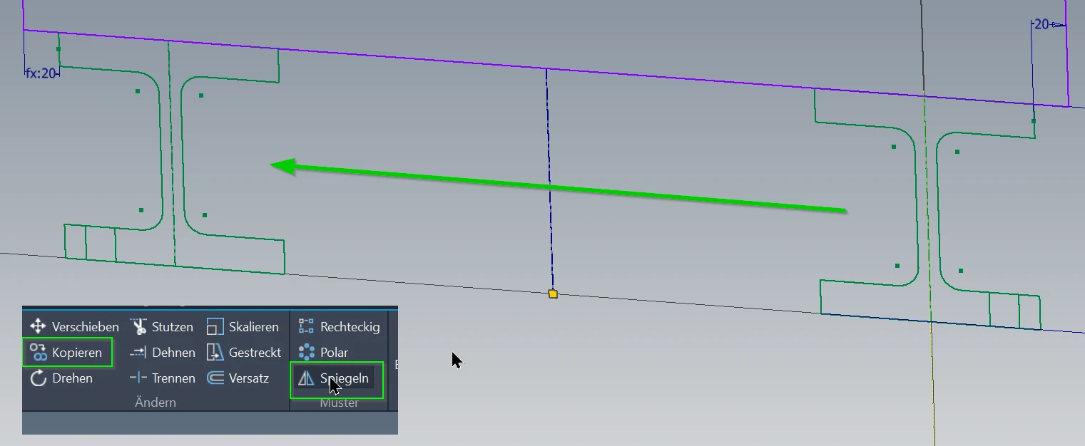
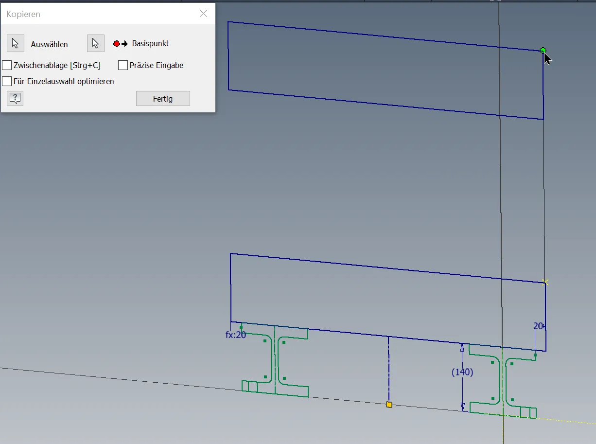
The block can then be manipulated and constrained like other sketch elements, for example you can copy or mirror it, and make the copies fixed somewhere with constraints.
Up to now it's still possible to create a reference dimension on the beam block from the outside and refer to it.
And this is where the difficulties begin
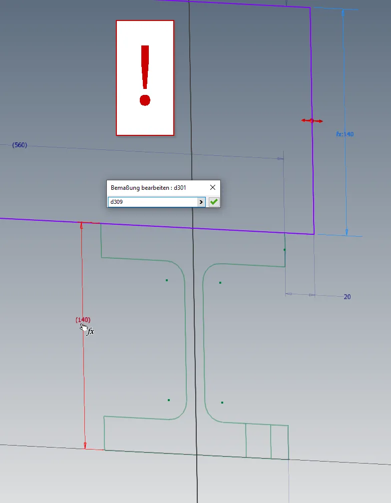
If you want to have further views of the beam depending on the first one, you can name the dimension appropriately in the block that is to define it and then use it in further views. What is not possible is to make a reference dimension on the beam block from the outside and refer to it inside another block. You get an error message that this would result in an infinite loop.
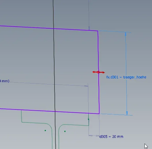
The side view, can still easily be multiplied as a block with this restriction. The height is synchronized in all instances of all views by the dimension equation.
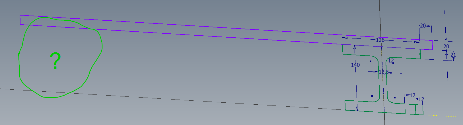
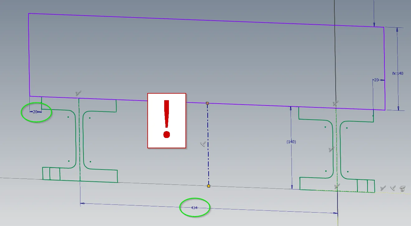
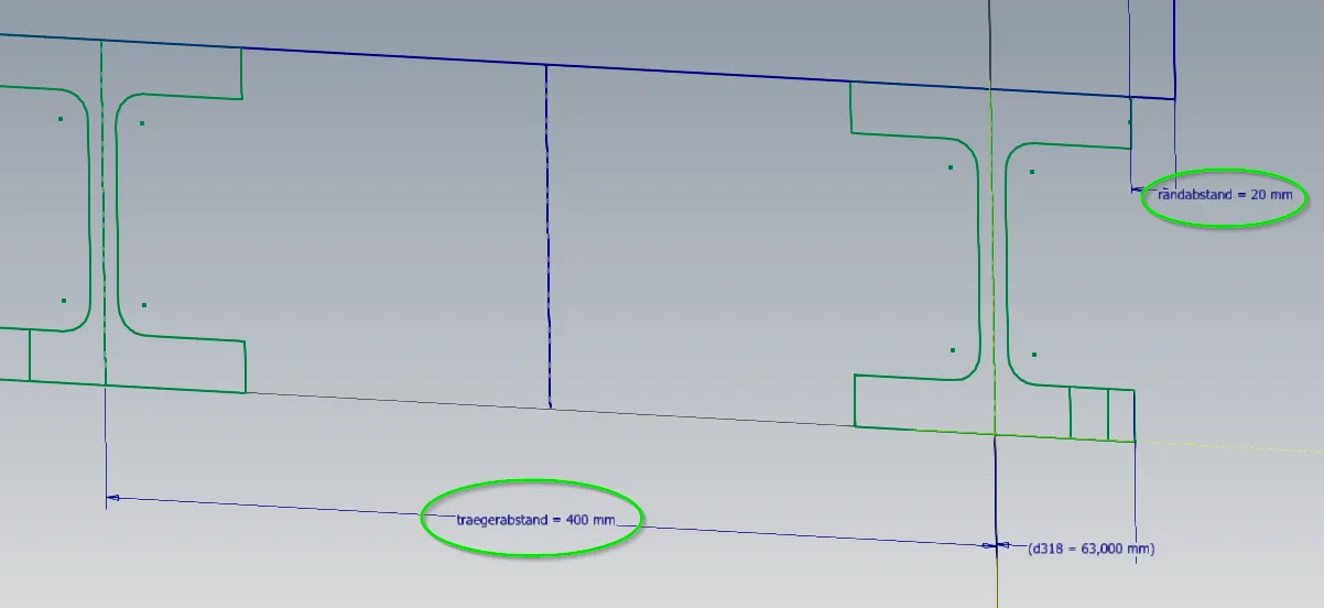
What doesn't work any longer is to dimension the cross beam indirectly to depend on the distance between the lower beams, because it is now a block. The following dimension would only be possible if the cross member wasn't in a block, i.e. the block is exploded or not created at all:
What does work here is the detour via the dimensional equation. For example, you can name the beam spacing, the beam width and the edge distance in the cross-section block or the higher-level sketch (if not a reference dimension) and then enter the width of the cross beam as equation, after the symmetric constraint of the crossections across the center line is deleted:
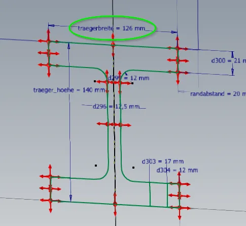
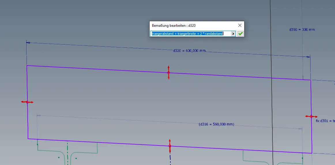
This way even element groups that have cross-dependencies can be put into blocks and multiplied.
Conclusion
The procedure shown last is of course quite complicated and only useful in special cases.
- Sketch blocks are particularly useful for components that appear multiple times, affect the rest of your design, but are not significantly affected by the surrounding design.
- If you have no or very simple interfaces into the block that can be solved clearly using parameters, there is nothing wrong with sketch blocks.
- If you need many identical instances of an element group, there are good reasons for using sketch blocks. In such a situation it makes sense to use them.
- On the other hand, if you have many relationships from outside the element group that determine the geometry of the element group, the relationship can hardly be implemented in a meaningful way if sketch blocks are used.
If you need more in-depth advice on CAD methods, please click on Contact.
You are also welcome to download the short presentation (sorry, only in German) on the topic. It may be used freely in unchanged form, including commercially, provided the source is acknowledged (license: CC BY-ND).
You can also download the model files in the finished state of this tutorial.
Click the links to copy to clipboard
This page: https://r-kon.eu/cad-skizzenbloecke.php
The video: https://youtu.be/CFwGY2RptLg (Youtube) / https://dai.ly/k4emvabhZnYrTwzD2Gj (DailyMotion)