Add details to top-down assemblies and prevent collisions
Details in skelettgesteuerten Baugruppen ergänzen und Kollisionen verhindern
Links on the topic: The Video on detailing skeleton models and collision avoidance at Youtube or DailyMotion and the short presentation (sorry, only in German) as PDF.
Efficiency boost: Detailing based on a skeleton-controlled assembly design
Once an assembly design has been set up as a skeleton-driven assembly, the top-down method shows its advantages. Details that affect several individual parts are only drawn once and derived in all parts. With a little practice, the design can be detailed very quickly and dimensional changes during the course of the work hardly require any effort.
Adding details across parts
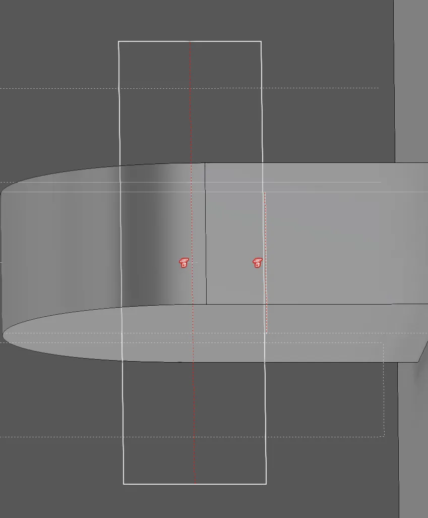
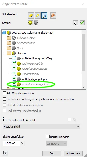
In the skeleton, new sketches are usually created for the additional details so that the sketches remain manageable. Only if there are already sketches with very manageable content in the appropriate context should existing sketches be extended. The already sketched surrounding elements needed as reference are first projected into these sketches. In the example (Figure 1.2) these are the edges of the bracket on the console, the fork on the arm segment and the pivot point of the arm segment.
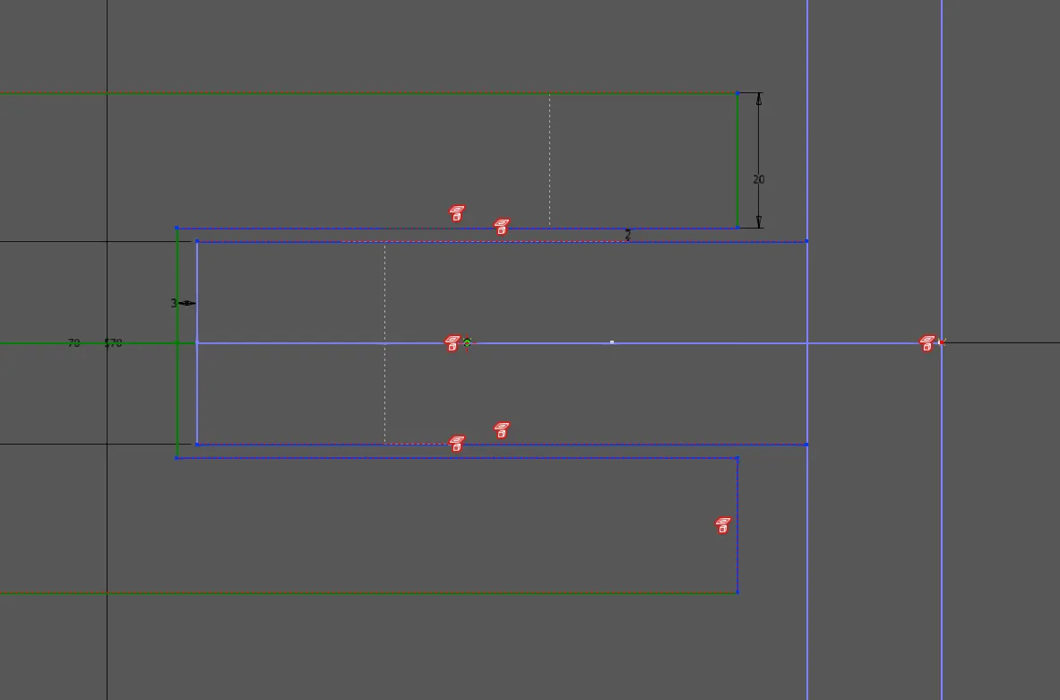
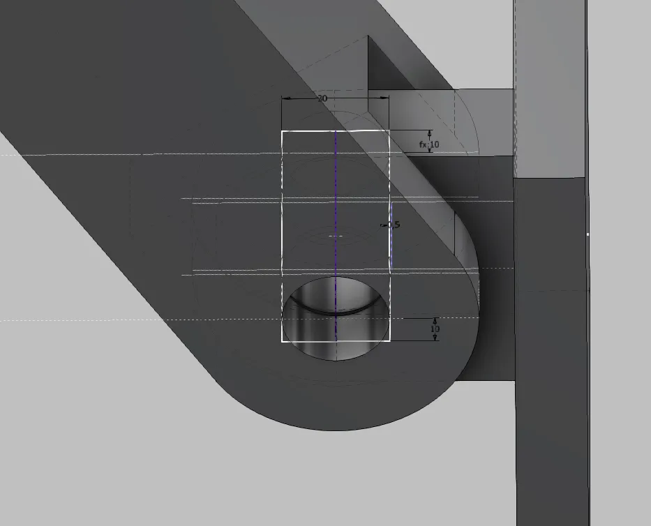
Now, as in Figure 1.3, the new details are drawn with reference to the projected elements: The bolt and a hole with some play for the bolt in the middle bracket. The outer brackets should have a fit to the bolt, i.e. the same nominal diameter, which is why the bolt line can be used for the hole here. In this sketch, for example, you could also accommodate sliding bushes, washers, axle holders, keys or retaining rings if the design requires it.
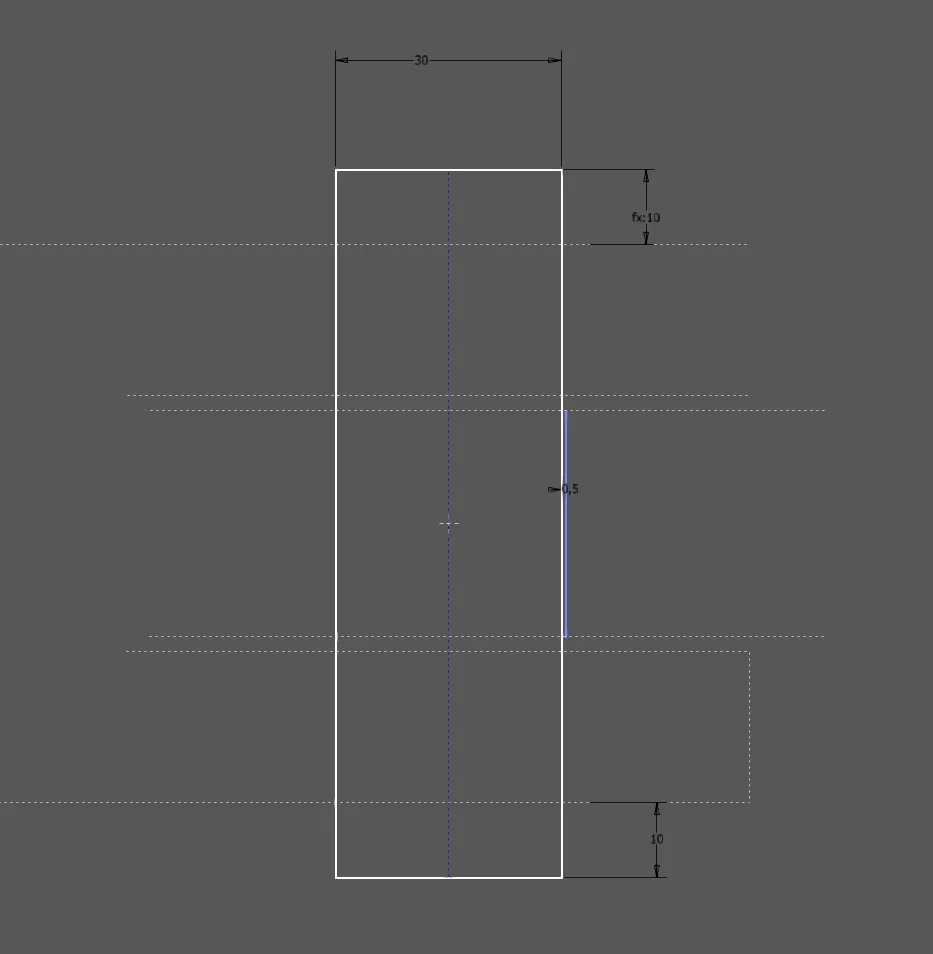
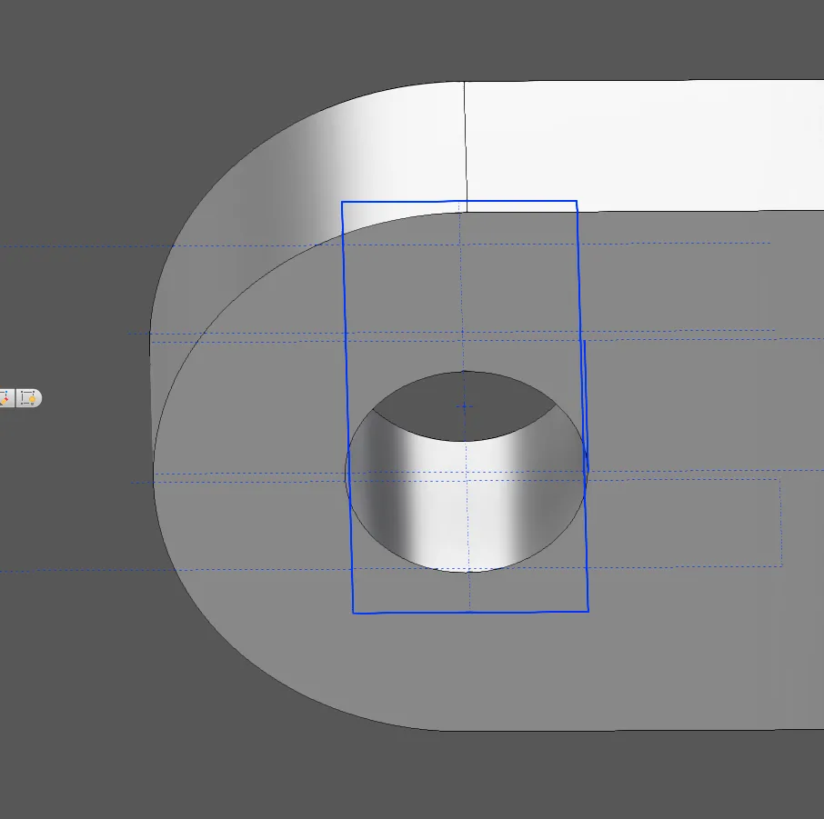
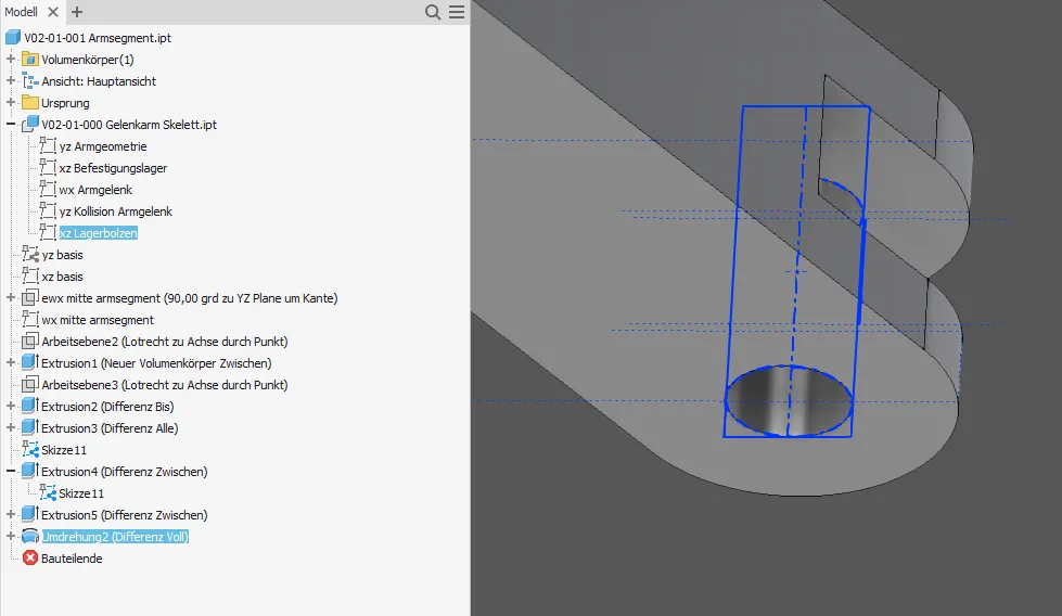
Then, if available, the base sketch is extended by projecting the required elements from the new derived sketch (Figure 1.6). In this case, only the hole outline is needed, you can also take the centerline with you, but actually it is already present in the part. Usually, a sketch must be created for the volume features, projecting elements from the base sketch or the derivation and drawing the required closed contour in it (Figure 1.7). In none of these steps should dimensions be created! The sketch geometry must be designed to remain stable even when dimensions are changed. Figure 1.8 shows the finished volume subtraction with derived sketch.
The fork at the end of the arm segment (Figure 1.9) is processed in the same way, only that here the outline of the bolt is projected.
The view of the assembly (Figure 1.10) shows that matching holes are now in the two parts of the joint. Even if the bolt diameter is changed later, the holes will always remain consistent.
Collision avoidance
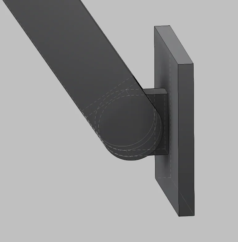
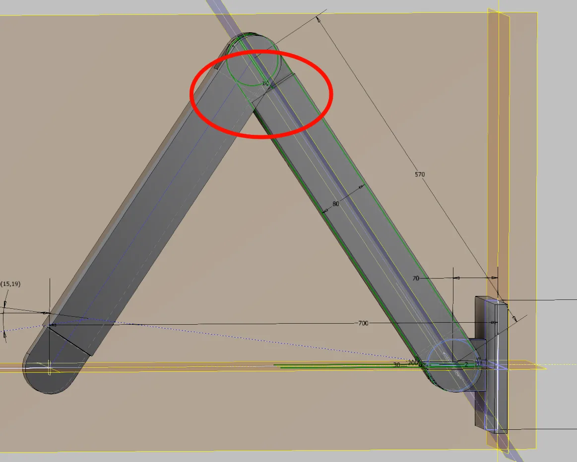
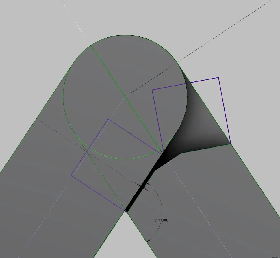
In the retracted position, the arm, as shown in Figure 2.1, still has a collision because it is less than 90° extended. Of course, this could be eliminated by manually moving the edge or by manually introducing a slope, but with dimensional changes, one would have to make sure that this collision is avoided again and again.
It is more elegant to sketch the collision situation in the skeleton and define the necessary material removal by dimensioning the required play. This way, when the segment geometry changes, the necessary space for movement will always be available.
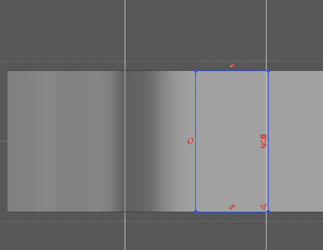
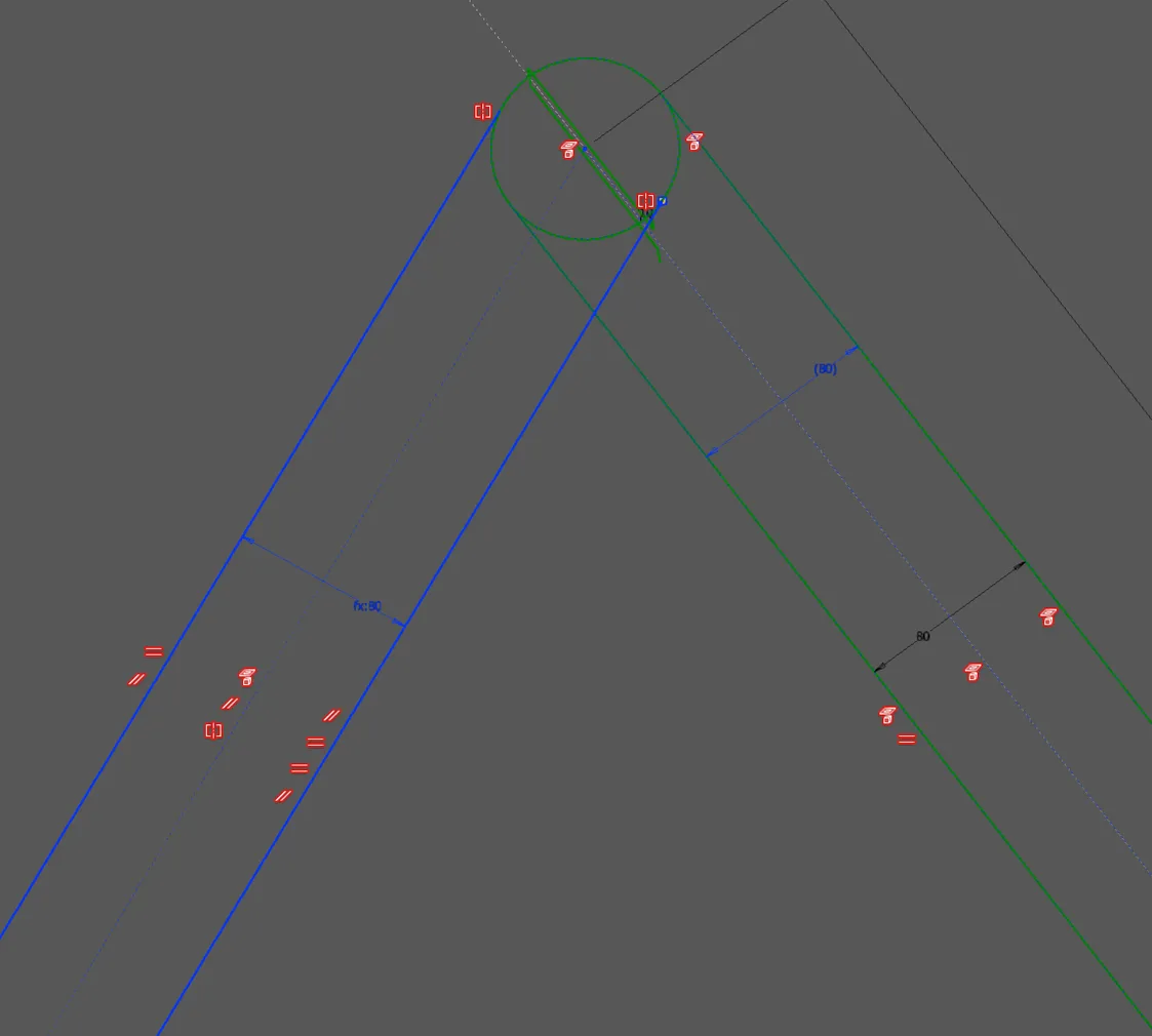
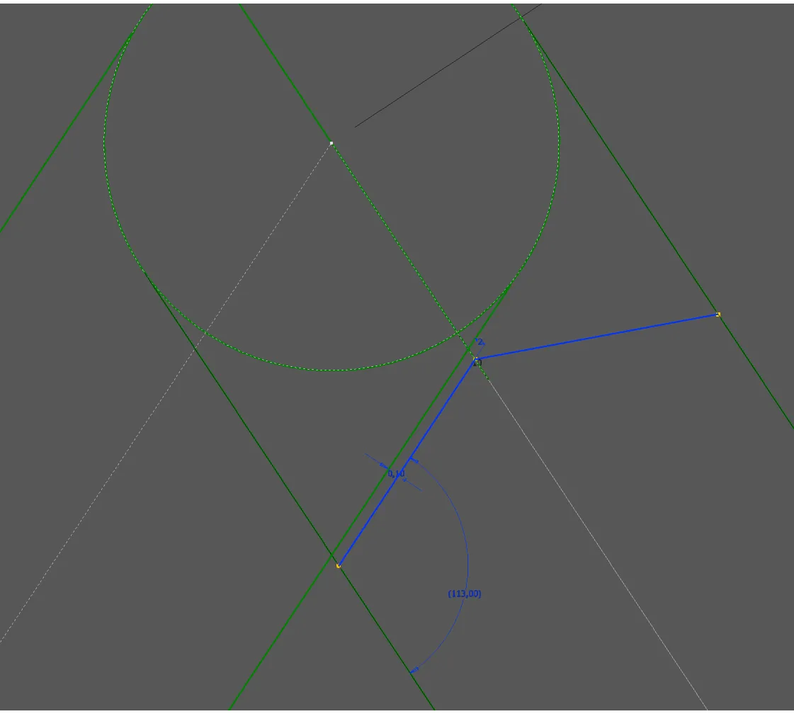
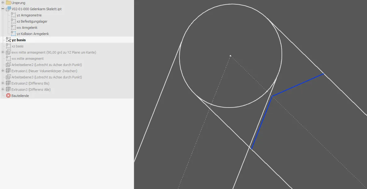
First, a new sketch for the collision situation is created in the skeleton, into which all elements relevant for the collision are projected. If the affected part geometries are not yet sketched or only in a different position, they must be drawn with reference to their original definition in the collision situation. In this example, the second arm segment is not sketched at all as a second copy of the first, so the colliding cross-section must first be drawn and referenced to the first copy (Figure 2.2). Then, as in Figure 2.3, the necessary material removal, in this case a slope, is drawn. You could simply draw a line parallel to the second segment with a dimensioned distance, but the angle would then be crooked. If you want to have a right angle, it is better to dimension an endpoint of the line and define a very small angle instead of parallelism, which brings the slope to be removed to a straight dimension (the reference dimension in the picture).
If you want the angle to automatically always assume a straight dimension, you can enter a rounding formula instead of a value that calculates the remainder of the reference dimension to the next whole number or to full tens with round().
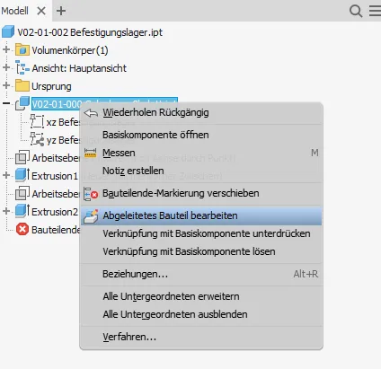
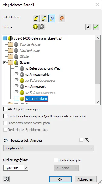
The sketch created in this way is again transported into the affected individual part, here the arm segment, as described above (Figure 2.4), and there the base sketch is extended with projections (Figure 2.5):
The lines obtained in this way are supplemented in a sketch with squares without dimensions, on the basis of which the slopes are removed on both sides (Figure 2.6).
Conclusion
By following this guide, the holes for the bolt and the cutout at the arm joint are linked via the skeleton and will always fit together or to the chosen design dimensions. The length of the associated video already shows how the workload shrinks when working based on a skeleton created and integrated once. I no longer need to manually transfer dimensions between the individual parts and check if everything fits. I quickly draw it in the skeleton and it fits everywhere, even if I change it dozens of times until the assembly is completed.
If you need more in-depth advice on CAD methods, please click on Contact.
You are also welcome to download the short presentation (sorry, only in German) on the topic. It may be used freely in unchanged form, including commercially, provided the source is acknowledged (license: CC BY-ND).
You can also download the model files in the finished state of this tutorial.
Click the links to copy to clipboard
This page: https://r-kon.eu/cad-details-und-kollisionen.php
The video: https://youtu.be/29D3n5Vy8Hc (Youtube) / https://dai.ly/k1QzlaGDmBWmcPzD2zd (DailyMotion)
