
Create geometrically stable sketches
How to create sketches geometrically stable and keep them intact even with larger changes
Links on the topic: The Video about stable sketches at Youtube or DailyMotion and the short presentation (sorry, only in German) as PDF.
Stable sketches - the basis for change-friendly model geometry
It is obvious that models that are to be changed after their creation or transferred as a copy into further variants must be adaptable with manageable effort. The decisive element for this are usually the sketches. This applies in particular to assembly models controlled by sketch skeletons with their many interwoven sketches. Troubleshooting in a skeleton-controlled assembly is a demanding and time-consuming task. Therefore, special emphasis should be placed on avoiding model-damaging errors here.
If sketches are geometrically unstable, changes lead to them being unsolvable. In the case of local changes, you usually get an error message directly and can cancel or undo. If a sketch includes other geometry, parameters or, in particular, external references, the program often only realizes when updating the dependent model that it is no longer solvable due to the change of the references. Such sketches can only be edited again with considerable effort. If you are unlucky, they may not even be displayed anymore, so you cannot see what went wrong and why, and you cannot access dimensions directly anymore. In addition, it may happen that you would have to change dimensions to fit each other, but cannot change each one individually because doing so would lead to an error without simultaneously changing the other.
Therefore, when creating the model, care should be taken to ensure that sketch geometry remains functional in the event of predictable changes. Some problems can also be avoided in advance with volume elements. However, repairing them is usually easier, so errors are easier to bear. In general, one should reference as little as possible to the volume bodies, so not much depends on them anymore. In this chapter I will show some examples as food for thought on how to avoid potentially unsolvable geometry.
Sketching slopes as surface sections
If a slope is essential for the geometry of a construction, it is usually sensibly integrated into the sketch of an extrusion instead of being created with the slope tool. However, if the slope is drawn as part of a closed contour, as one is used to from 2D drawings, serious errors can easily occur when dimensions change. Much depends on the dimensioning systematics and Inventor is surprisingly error-tolerant compared to Creo.
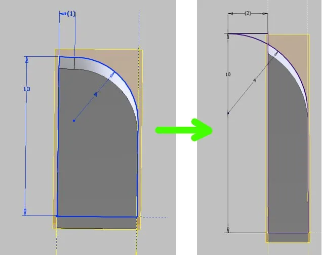
Figure 1.1 shows what can happen to a sloped contour when the proportions of the contour change. If the plane on which the lower line lies is moved, the line drawing can "knot up". Inventor then takes a functioning closed contour as a base surface for the volume at its own discretion, while Creo simply rejects processing. Further sketches that may reference the sketch shown may behave unexpectedly because the lower line has reversed its direction. In this simple example, it is easy to see that the slope would also have to be set further down to repair the part, but in a more complex context, the consequences can become unpredictable.
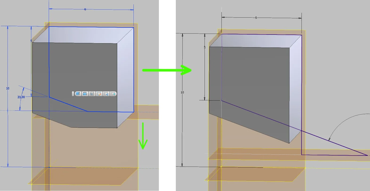
It is more skillful if the basic contour is drawn closed without the sloped section in the basic sketches and the slope line remains largely independent as shown in Figure 1.2. It can be fixed to the outer dimensions of the contour to define the length. This prevents a "flipping" of the contour.
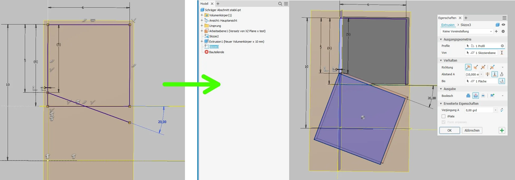
Inventor could also directly create a sloped volume body based on this sketch, because it recognizes the closed surface even though the line drawing is not closed by points. However, the volume of the entire body would fail if the slope line is pulled out of the rectangle. If the dimensioning allows for the slope to completely disappear (and it is even constructively desired that it is optional), a separate extrusion body should be created for the slope. In Creo this is mandatory.
Independent extrusions based on individual lines are best created by projecting the line into a new local sketch and adding it to a square. This way, no additional dimensions are needed and a very stable geometry is achieved. If a square does not fit, of course other shapes can also be used. The square is extruded between the surfaces of the basic body.
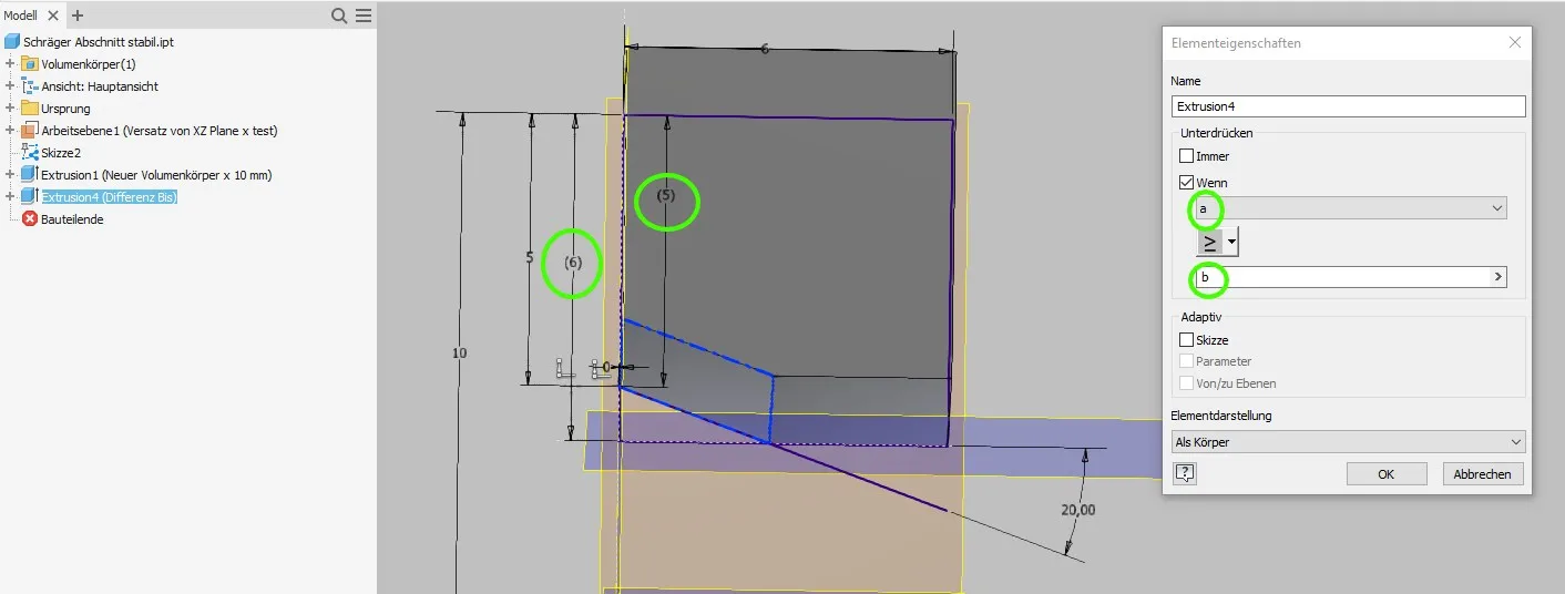
If the slope is to be optional, an additional step is required in Inventor (Figure 1.3). Inventor refuses to calculate extrusion bodies that only go through empty space, i.e. do not cause a volume change. To prepare the model for an allowable "emigration" of the slope, we need two parameters and/or reference dimensions to control a conditional suppression. In the example, the extrusion is suppressed as soon as the distance of the slope start from the upper contour line is greater than or equal to the height of the contour, because from this value no material removal takes place anymore. In Creo, this step would not be necessary, here Creo is more tolerant and operates on the motto "Nothing minus nothing is still nothing, it doesn't matter".
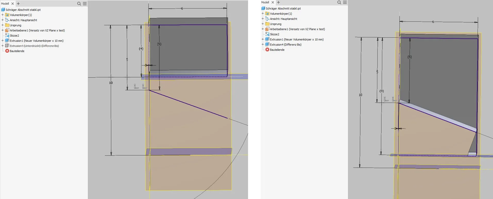
The result is a very stable model that does not fail even with significant changes, as shown in Figure 1.4. The geometric result when the body is greatly elongated is certainly not desired, but the error is very easy to recognize and solve without much damage. By increasing the extrusion body, permanent remedy would also be possible here.
Cutting circles
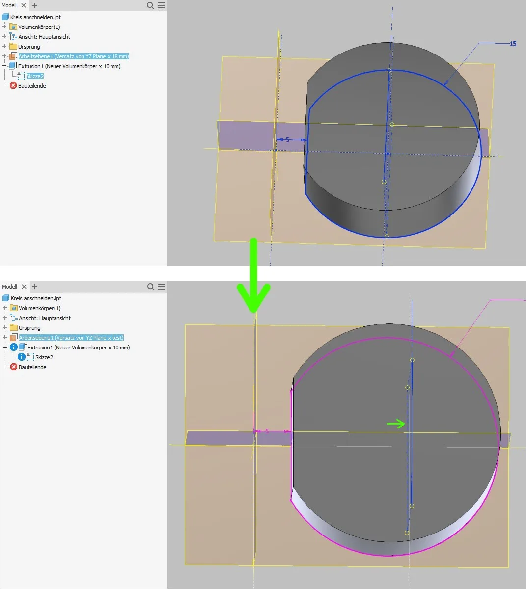
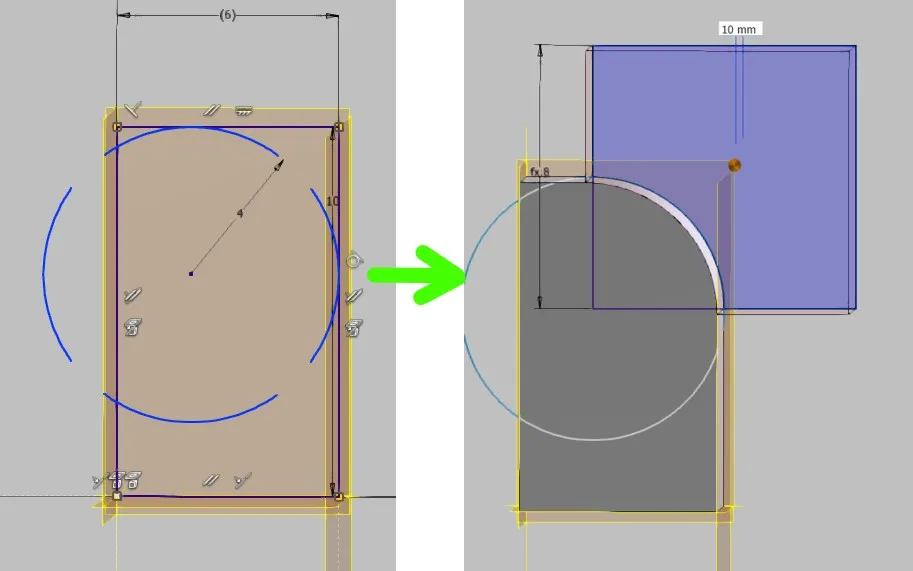
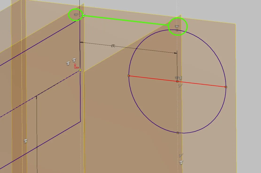
Often round or cylindrical bodies need to be flattened, for example because a space limit is closer to the center than the radius. Interrupting the circle and connecting the ends with a line ("secant") is an extremely unstable solution. If the underlying geometry is changed so that the construction space limit moves further away from the center than the radius, the contour becomes unsolvable. In the following example (Figure 2.1), the center of the circle is fixed to a parameter-controlled vertical plane (to simulate an external reference) and the construction space limit is defined from outside the circle (dimension 5). If you move the center of the circle away from the section as shown in the image or reduce the circle radius, the sketch is broken. In this simple sketch, the cause is easy to find and fix, but in more extensive sketches it is tedious to identify and delete the problematic conditions and dimensions to make the sketch solvable again. If you set the dimensions so that the cutting line lies exactly on the circle as a tangent, the sketch is even permanently destroyed and cannot be revived by correcting the dimensions in Inventor 2020 (oh a bug!).
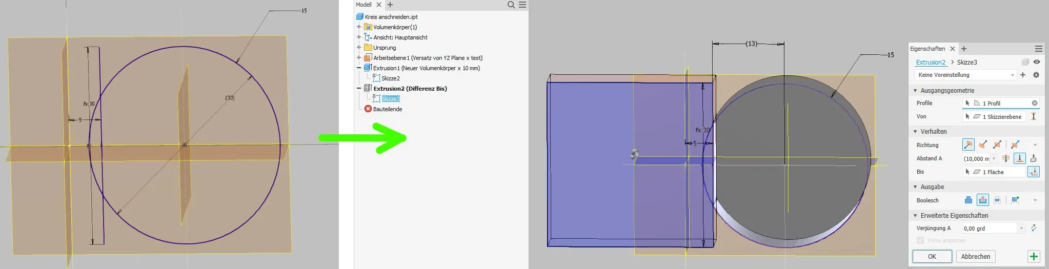
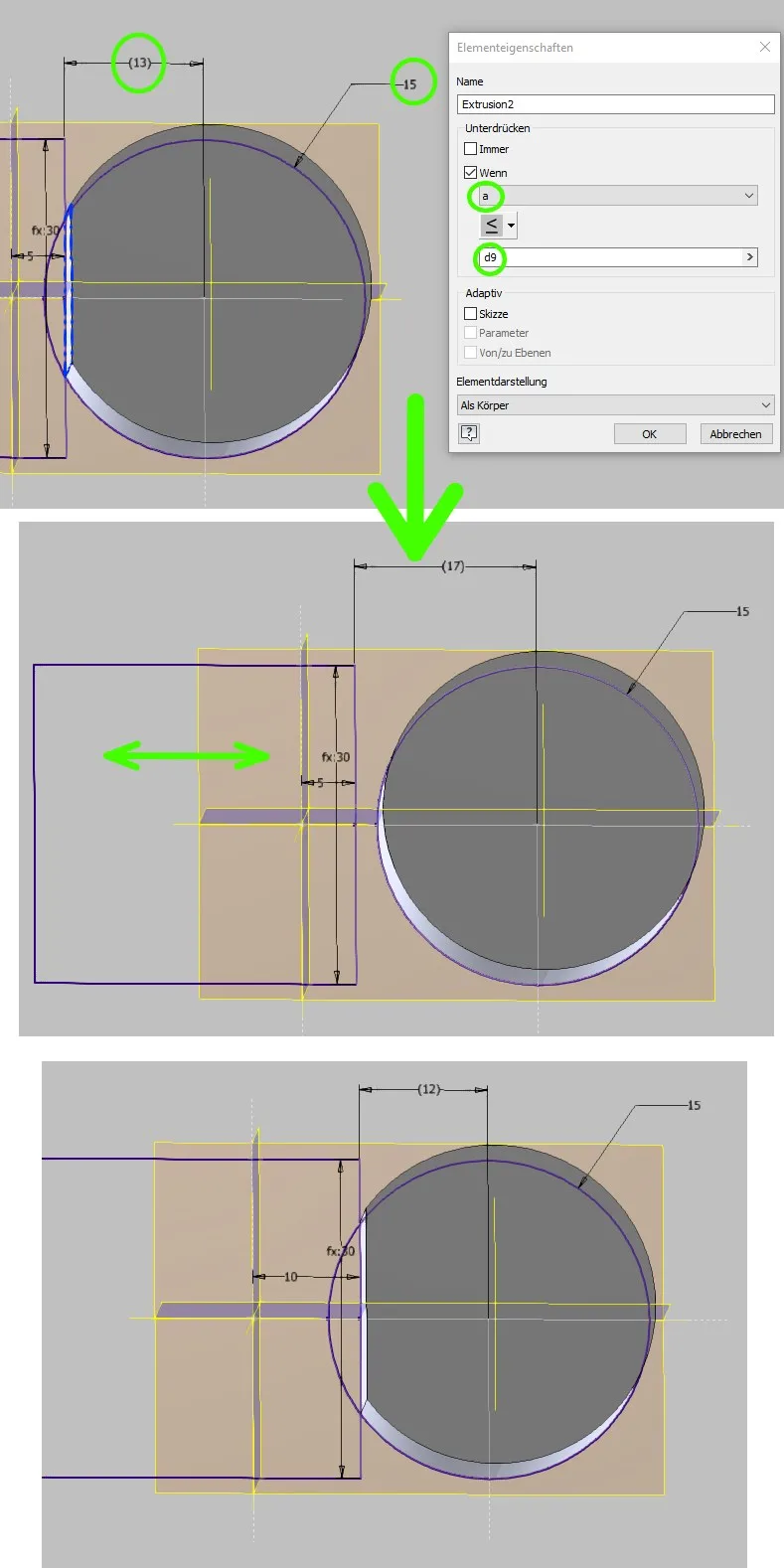
To prevent these fatal errors from occurring, the circular contour must always remain closed. Circular arcs are generally very unstable and should therefore be used sparingly. To cut the circle, an independent line is created in the controlling sketch, whose length (at least) equals the diameter of the circle. This line is supplemented to a square as in the slope example, extruded and provided with a conditional suppression in Inventor if necessary. (Figure 2.2)
Here too, the result is a stable geometry for all foreseeable dimensions. The flattening of the solid is optional, the model can be safely controlled via the sketch dimensions and external references.
Fillets based on sketches
If fillets are essential for the geometry of a part (usually these are particularly large fillets), it may make sense to draw and extrude them instead of using the fillet tool.
Here too, the well-known problem of the "knotted" sketch can arise. Sometimes it also happens that the circular arc flips and suddenly lies outside the contour in a mirror image. Inventor finds a surface, but you don't know exactly which one beforehand; Creo would reject processing. In addition, one of the lines adjacent to the fillet can become zero length, which is geometrically impossible. Interestingly, Inventor does not give an error for this anymore in version 2021; however, doubts about the stability of lines with zero length are still appropriate. In more extensive or dependent sketches, unexpected results may occur due to the reversed or missing line.
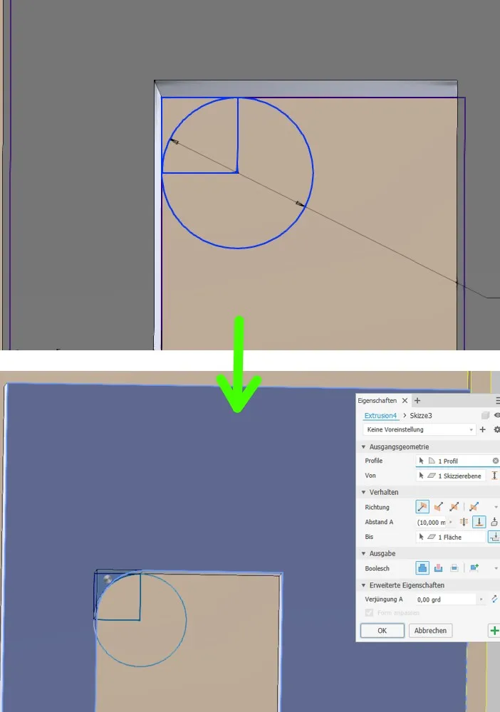
Here too, the stable solution starts again with a full circle in the defining sketch. For external fillets, a square connected to the circle can serve as an extrusion body, as shown in Figure 3.2, and for internal fillets, a merged extrusion as shown in Figure 3.3.
Both variants work stably even if the partial contour no longer allows a complete double-sided tangential fillet. The controlling dimensions remain accessible even with unrealistic inputs.
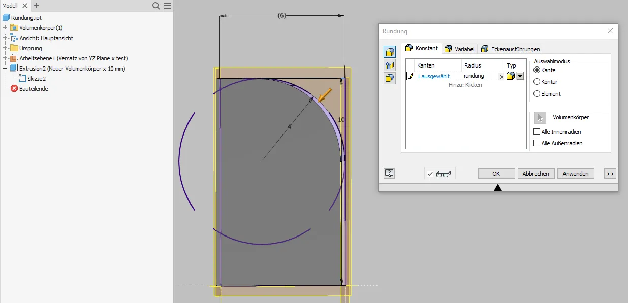
If it is ensured that a fillet defined in the skeleton can always be completely executed due to the foreseeable size ratios, the fillet tool can also be used and a (reference) dimension from a sketch can be used as the radius, as shown in Figure 3.4. However, it should be noted that the fillet tool moves the center point when one end of the fillet reaches the edge of the part, which can lead to significant geometric distortions for relatively large fillets.
Lines of length 0
If lines in sketches do not have an explicit length specification but are determined indirectly by references and dependencies, it must be ensured that they do not become length 0 with expected changes. In the example (Figure 4.1), construction lines were used to synchronize the height of the circle center and the diameter with the previously drawn side view (which could be a groove or an offset view of a bolt, for example). If the planes are moved so that the side view is exactly in the center of the circle, the line length becomes zero. Even if Inventor allows this now: Lines of length 0 cannot be healthy.
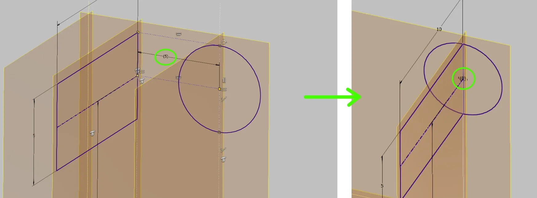
Preferably, either the use of alignment conditions (horizontal / vertical) as shown in Figure 4.2 above or the creation of a line oriented to the target with stable length (+ possibly point lying on it) with coincident conditions (Figure 4.2 middle)
Conclusion
There are certainly many more ways to create unstable geometry and at least as many ways to avoid it. These relatively elaborate methods are only worthwhile where it really matters for the potentially unstable elements and therefore have to be provided in the controlling skeleton.
In general, it is always worthwhile to think about how the model will behave with changed input parameters when building a model and whether the created geometry will allow that.
If you need more in-depth advice on CAD methods, please click on Contact.
You are also welcome to download the short presentation (sorry, only in German) on the topic. It may be used freely in unchanged form, including commercially, provided the source is acknowledged (license: CC BY-ND).
You can also download the model files in the finished state of this tutorial.
Click the links to copy to clipboard
This page: https://r-kon.eu/cad-stabile-skizzen.php
The video: https://youtu.be/zFkWhP8hQ8o (Youtube) / https://dai.ly/k4yapdfvgeLLIuD2FMG (DailyMotion)