
Creation of a skeleton-controlled assembly in 3D-CAD
Creating the required files, creating geometry and dependencies in skeleton modeling
Links on the topic: The Video about creating a skeleton-controlled assembly at Youtube or DailyMotion and the short presentation (sorry, only in German) as PDF.
Procedure for setting up the assembly structure
In this tutorial I explain the basic structure of skeleton controlled assemblies. Skeleton modeling is my favorite variant of top-down modeling because it works very clearly. The procedure consists of 5 basic steps, but they do not necessarily have to be worked through in a strictly sequential manner. It makes sense to follow the scheme at the beginning and later jump between the steps as needed.
- Create (skeleton) part: In Creo this is a special file type, in Inventor simply a part
- Sketch input conditions and draft of the assembly (relevant states and relationships) in skeleton part.
- Create assembly + individual parts derived from the skeleton part
- Create volume in the individual parts, assemble assembly
- Detail
Create the skeleton part and sketch the draft
Working in the skeleton should begin as early as possible in the design process. You build an evolving structure in which changes can be introduced continuously with little effort, an agile structure, so to speak. The skeleton is at the same time the draft that many otherwise do on paper sketches or in separate CAD files. You can save yourself this detour if you build a clean skeleton structure right from the start and use this as the basis for the design.
The skeleton begins with the necessary initial conditions and the first rough ideas for the design. During further processing, the skeleton undergoes an evolution to the finished, detailed engineering design.
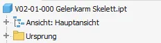
So first the skeleton part for the assembly to be designed is created. The part is given the name of the associated assembly file with an appended tag for skeletons, I prefer plain text (in German) "skeleton" (Figure 1.1).
As an example, I'll use a simple fantasy assembly: an articulated arm bolted to a surface, the end of which is designed to move linearly. The environmental conditions and functional parameters that become determinative for the assembly are sketched at the beginning of the skeleton. This requires some discipline, especially if some of the parameters are not yet known numerically or if there is a comparison template in which the result of the design is anticipated. For parameters that are not yet known, elements with estimated dimensions must be generated, which are then updated later in the course of the project; driven dimensions are used for comparisons ("reference dimensions" in Creo). In this greatly simplified example (Figure 1.2) I use a vertical screwing surface and a desired horizontal traversing path as input conditions. In the case of real constructions, these sketches would usually be more extensive. For the creation of different sizes or variants, one can also create list parameters and related iLogic in the skeleton, so that the input conditions become configurable via drop-down in the parameter list to quickly adapt the assembly. Increments of individual parts according to the standard could be programmed directly into the skeleton. A link to spreadsheets is also possible.
Then the relevant states and functional relationships of the assembly are depicted in separate sketches and, if necessary, working geometry. For good modifiability it is important to keep the sketches small and to name them meaningfully. Only those elements that belong together functionally should be shown together in one sketch. It can often be useful to draw a portion of a part in one sketch and another portion in another. Each dimension may only be defined once in the skeleton, later instances of the respective geometry refer to the previously defined dimension by projection (or equation if necessary). It also makes sense to immidiately provide dimensions that come from technical calculations or are required for them and, if necessary, even to create them as named parameters.
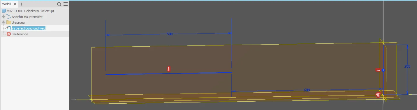
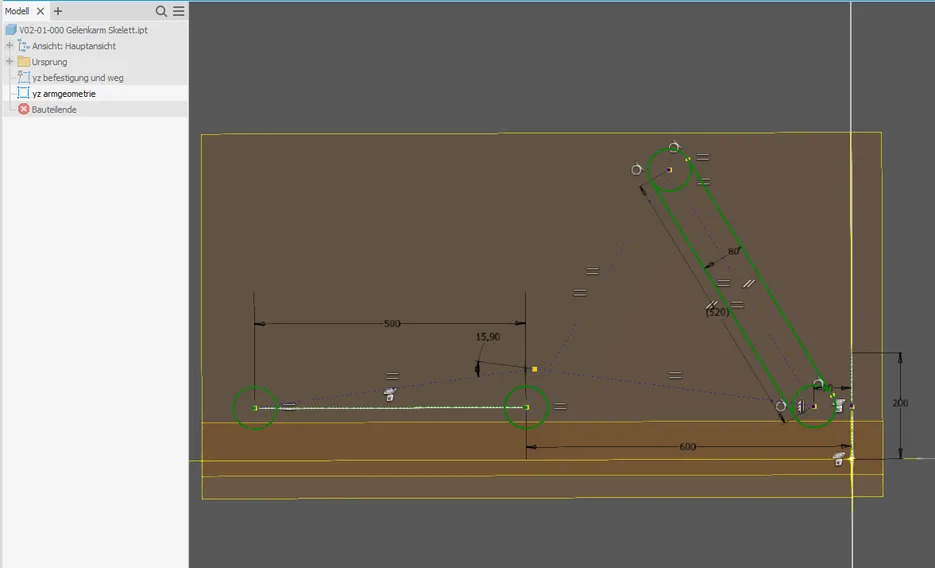
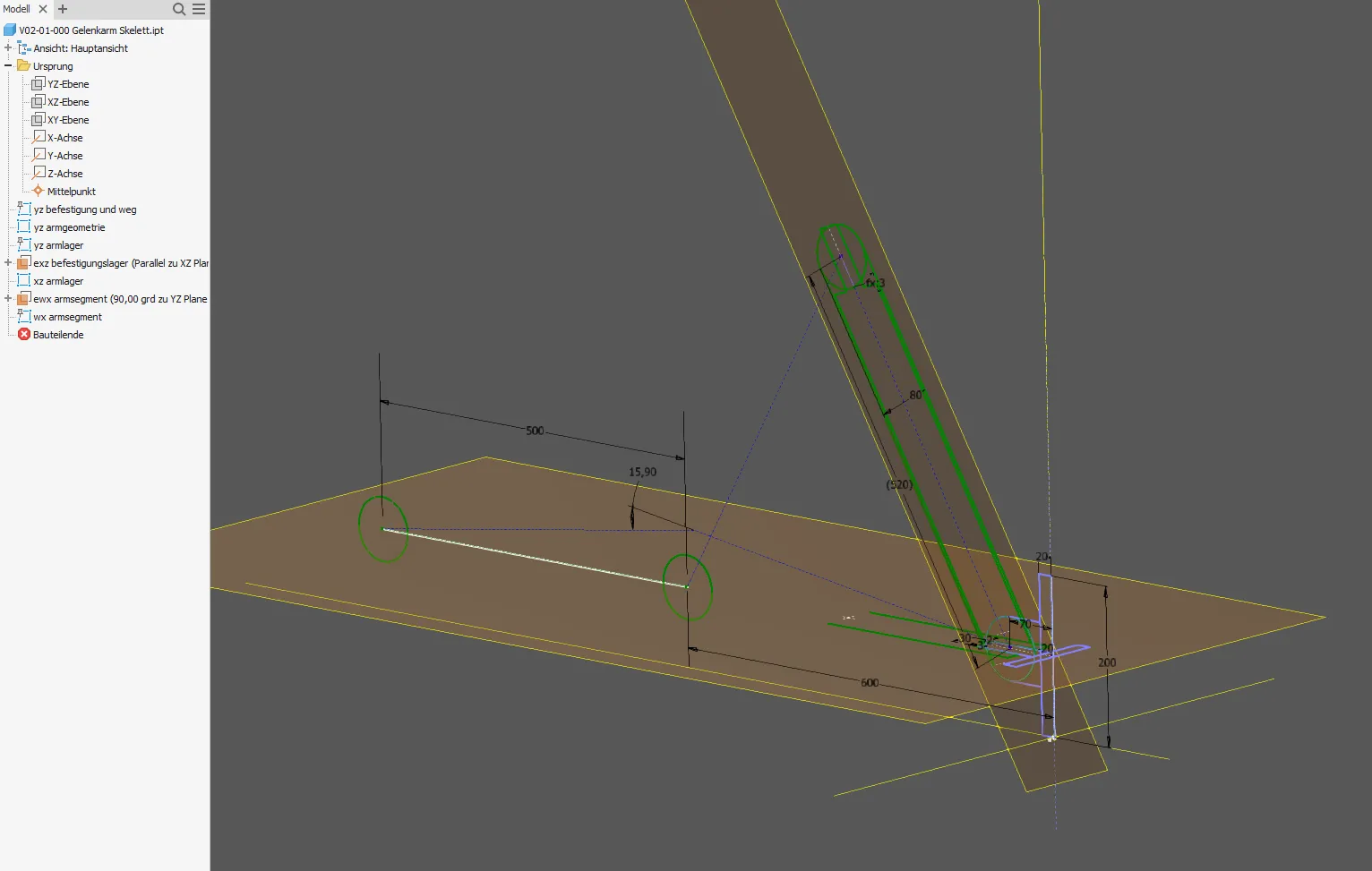
I want to have two arm segments of equal length, whose center lines from joint to joint I draw and equate (Figure 1.3). I draw in both relevant end positions instantly; since there are no body edges, construction lines are recommendet for symbolic elements such as the center lines. Sketch constraints link the various states together. The required input geometry is brought into the sketch as a projection. The ends of the arm segments should be round; so that the sketch doesn't get too unstable, I draw full circles instead of tangential arcs. I'll do a separate tutorial on the subject of "stable geometry". The mounting bracket for the arm is drawn in a separate sketch (Figure 1.4).
All pre-existing elements are projected into new sketches and views if something related to them is to be drawn there. To align sketches such as section views with the centre or position of existing elements, work planes are created on these elements. Dimensions that are to be the same at different points are equated with sketching conditions. In Figure 1.5 the skeleton is ready so far:
You could also make provisional volumes here in order to visualize or simulate something; however, these should then be deleted again or set to zero mass when the real part is created. Further details such as bolts, sliding bushes, etc. can easily be added later.
Create assembly and individual parts
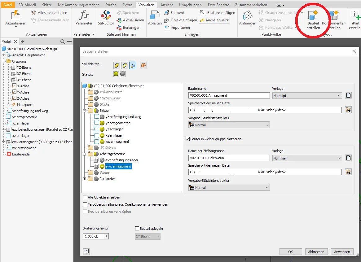
Creating the individual parts by derivation of the relevant elements and placing them in the assembly that may still have to be created can be done very conveniently in Inventor in one step with the "Create component" function, which creates derived components (Figure 2.1). With the respective option checked, the parts will be placed in the specified assembly, which will be created automatically even if it doesn't exist yet (Picture 2.2). It would also be possible to manually create a part and from there call the "Derive" function and select the required elements from the skeleton.
It"s not as convenient in Creo, there you would have to create a publishing geometry for each part in the skeleton and then import that into the individual part using copy geometry and manually insert the part into the assembly. With Inventor it is also reasonably safe to derive working geometry, in Creo I would strongly advise against it because that often leads to errors that cannot be analyzed.
Which elements are transferred with the derivation or publication geometry can be adjusted later in both systems.
The skeleton must be inserted and grounded to the origin manually in Inventor also. This isn't mandatory, but later during assembly it can be useful if you want to constrain parts with planes and axes defined in the skeleton; it is also useful to have the definitions of the assembly directly at hand. As long as you don't need it, you switch it invisible. This is where Creo is a bit more practical: skeleton parts are automatically placed at the beginning of the tree and at the origin.
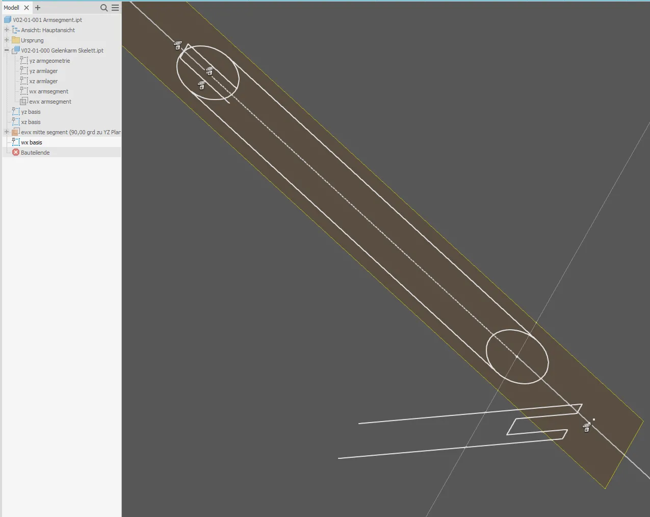
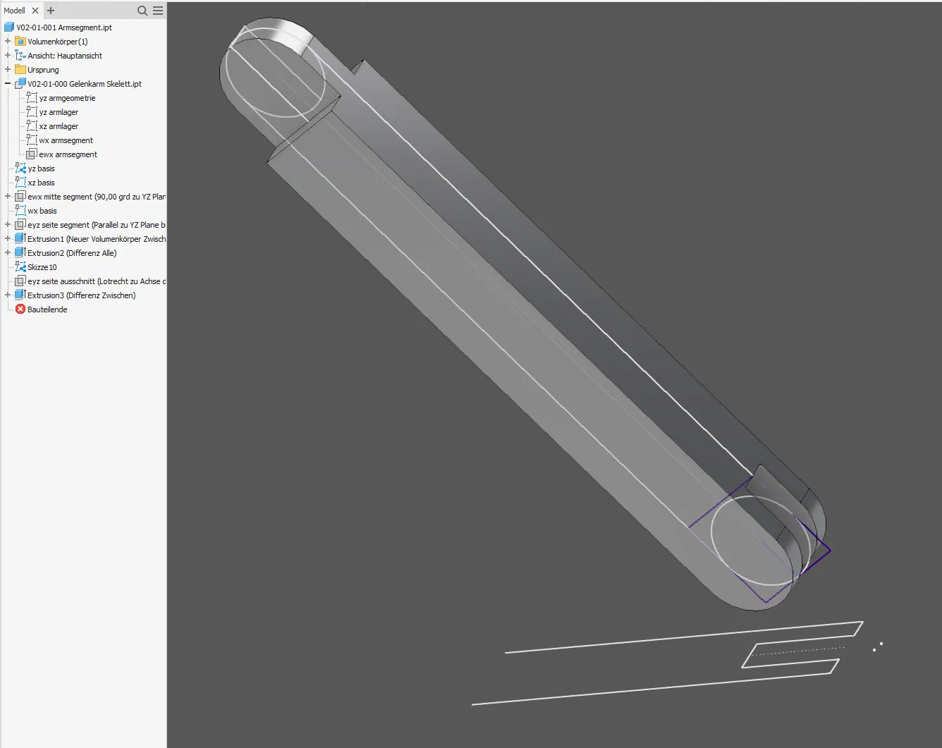
Now you can create the real geometry, so to speak, in the parts. In principle, we could reference directly to the derivation, but this can lead to difficult-to-solve errors in the case of changes in the skeleton. In Creo in particular, the exclusively projected basic sketch (Figure 2.3) is therefore essential. Inventor is more helpful with troubleshooting, so you can save that in simple parts. In general, one should reference to the derived part as little as possible. For example, inclined planes for base sketches should be built on previous base sketches instead of the derivation. Therefore, once all the required projections have been made, all skeleton elements in the derived part should be switched invisible. The volumes are then created on the base sketches (Figure 2.4)
Careful attention should be paid to what elements are being projected and whether they are stable references. Local references are typically more stable than external ones, sketches and work geometry are more stable than volumes.
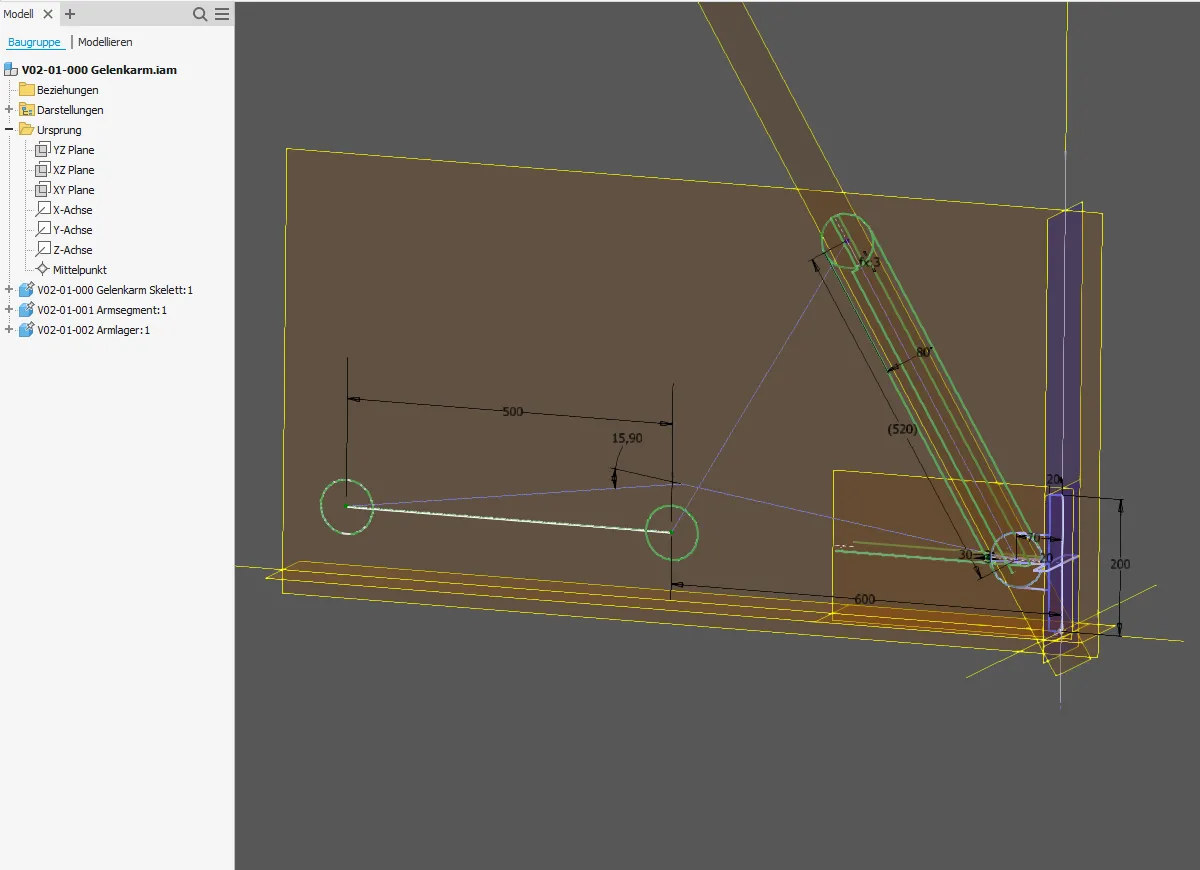
In the assembly, the parts immediately appear at the position drawn in the skeleton because everything is related to the same origin. As long as nothing is to move, the individual parts can simply be grounded to the origin; you can also create redundant assembly constraints at interfaces to increase security. This is, so to speak, the equivalent of the reverse-calculation. If a part is used multiple times, you simply insert it accordingly. If necessary, you can also create positioning references in the skeleton on which to place parts, such as the end of the second arm segment in this example.
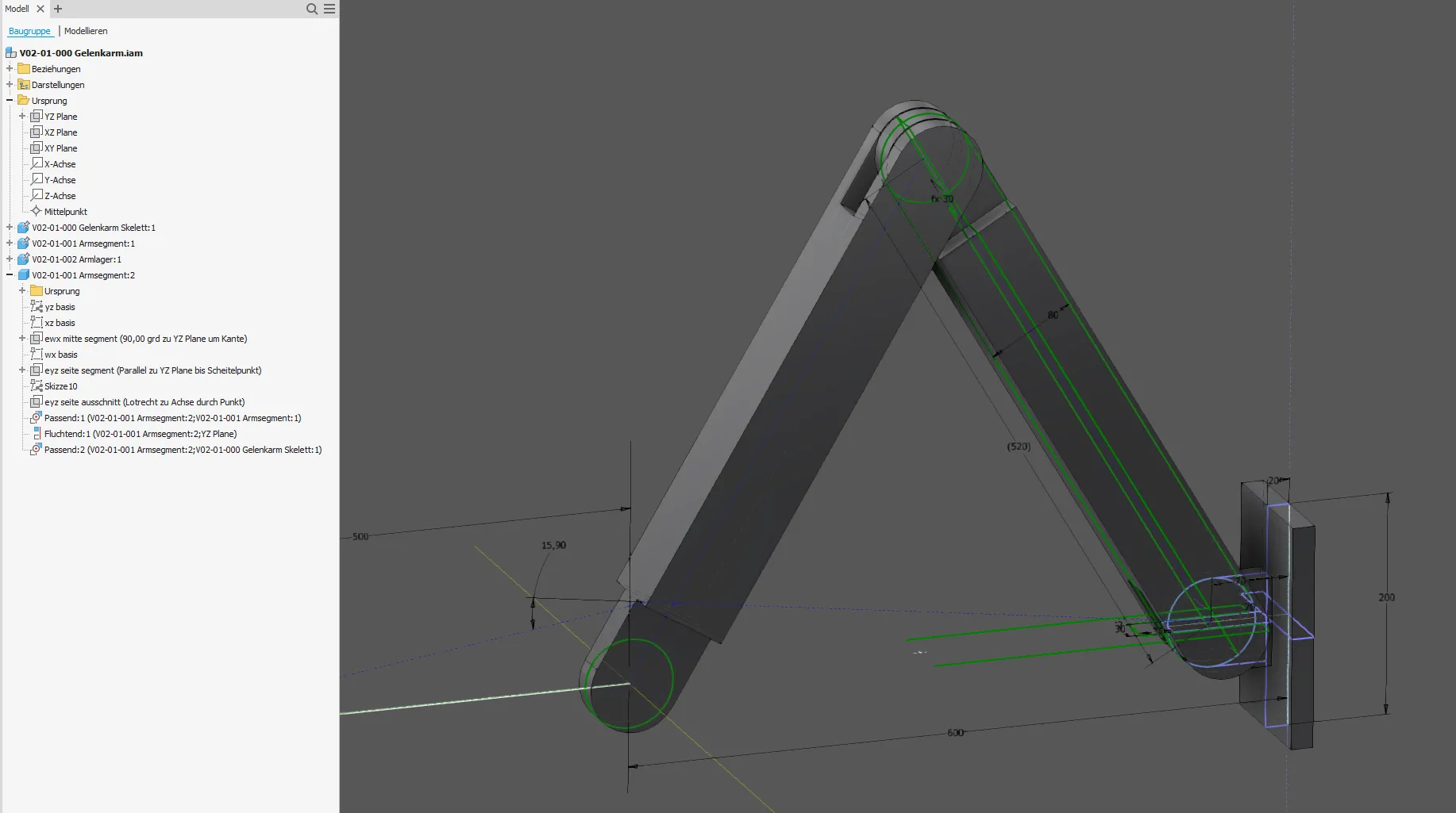
This assembly can now be completely controlled and modified from within the skeleton.
That was the guide on how to create simple skeleton controlled assemblies. Have fun trying it out.
If you need more in-depth advice on CAD methods, please click on Contact.
You are also welcome to download the short presentation (sorry, only in German) on the topic. It may be used freely in unchanged form, including commercially, provided the source is acknowledged (license: CC BY-ND).
You can also download the model files in the finished state of this tutorial.
Click the links to copy to clipboard
This page: https://r-kon.eu/cad-aufbau-skelettgesteuerte-baugruppe.php
The video: https://youtu.be/K1tplCkS9Ro (Youtube) / https://dai.ly/x8pdwsi (DailyMotion)