
Control chamfers and fillets with sketches
How to couple chamfers and fillets with sketch skeletons and transfer them to the solid part
Links on the topic: The Video on sketch-controlled chamfers and fillets at Youtube or DailyMotion and the short presentation (sorry, only in German) as PDF.
Functional dependency between chamfers and fillets
When parts are joined, it must be noted that inner edges of contact surfaces usually do not have ideal edges, but rather have a small rounding or are broken due to manufacturing. Sometimes, a larger radius is even intentionally provided to reduce stress. In the case of a precise and form-fitting connection, the counterpart must then have a sufficiently large chamfer on the corresponding outer edge to avoid collisions. When assemblies are adjusted during the design phase or during modification constructions, it is easy to forget one part when making changes at such interfaces. Therefore, this important relationship should be represented in the sketch skeleton to avoid surprises during assembly.
In the video on stable geometry, I showed some examples of how circular arcs can break. This results in the need to represent the chamfers in the sketch skeleton differently than with circular arcs, and preferably also without tangential conditions. Once the rounding is drawn, the dependent chamfer line can be easily added.
Draw radius and chamfer in the skeleton stably
In the example, a ring or gear, drawn in red, is to be fitted onto the green part, a shaft. Due to stress, a large radius must be present on the shaft shoulder. The main contours of the parts are generally drawn with ideal corners (Figure 1.1).
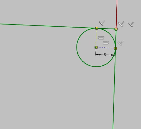
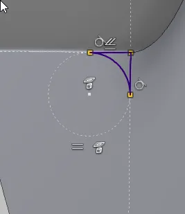
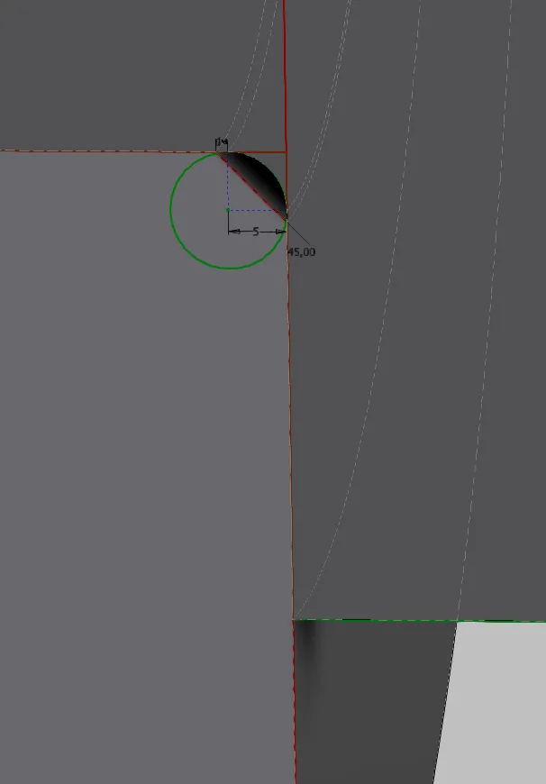
First, the required radius is defined and represented with two construction lines connected to a corner, perpendicular to the tangent to the lines bordering the corner. With the center on the corner point of the two lines, a full circle (arcs are unstable) is drawn, whose radius is set equal to the line length or is set coincident with the end of a radius line (Figure 1.2).
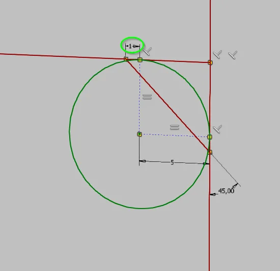
The chamfer on the disc must now have at least the same distance from the ideal corner as the radius is large. Making both exactly the same size will only result in reliably mountable parts if the radius is toleranced negatively and the chamfer positively. This would be rather cumbersome, so it makes sense to construct a sufficient distance that makes an exact tolerancing unnecessary.
Transfer radius and chamfer to the components
In the individual parts, the respective required element, i.e. the line of the chamfer or the circle of the rounding, must be projected from the derived assembly skeleton into a local sketch.
Basically, there are two obvious ways to create radius and chamfer:
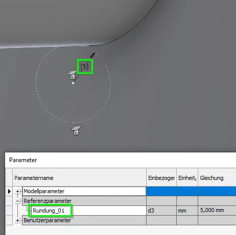
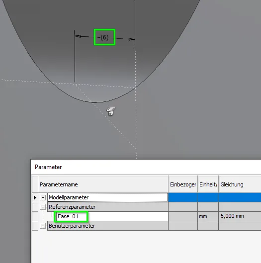
- The projected contours are dimensioned with a reference dimension (or several depending on the nature) and the chamfer or rounding is created with the respective feature. The reference dimension is then entered as a dimension in the feature. This is quick, but can become confusing with a larger number of such transferred dimensions. A consistent naming and numbering of the reference parameters and features is required.
- The projected contours are directly taken over to create a profile sketch, and instead of the chamfer and rounding features, an extrusion, a rotation or a sweep is used. This is more complicated to produce, but it is still easy to understand with a larger number of such features.
Variant 1, transfer using reference dimensions, is shown in Figures 1.4a and 1.4b.
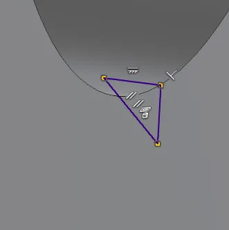
In variant 2 (Figure 1.5), a rotation is created on a profile sketch with the projected contour.
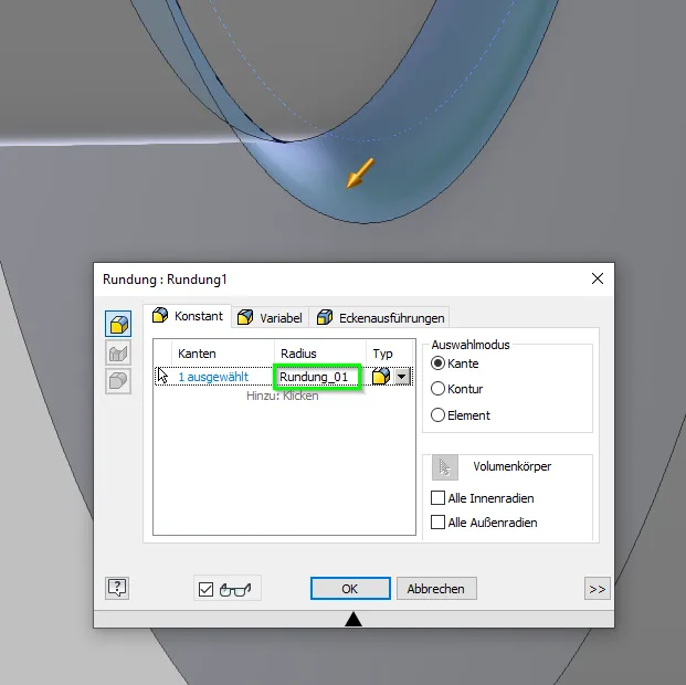
The same procedure is applied to the chamfer. Figure 1.6 shows solution 1, the reference dimension sketch, whose reference dimension is used in a chamfer feature, and Figure 1.7 shows the profile sketch, solution 2, on which a rotation feature is created.
The result is the same with both variants: Rounding and chamfer are controlled by the skeleton and always fit together in both affected parts. If it is also specified in the skeleton with iLogic which rounding radius is assigned to which shaft diameter, chamfer and rounding are automatically set correctly for all sizes of a series.
Conclusion
For connections that are to be constructed in a number of sizes, a lot of work and potential for errors can be saved by controlling the chamfers and fillets with the methods shown and possibly also assigning the fillet size size-dependently with iLogic.
But even for single-piece constructions, this approach is worthwhile at least for highly stressed cross-sections, because the radius is often iteratively changed on the way from design to detail construction with refinement of the calculations.
If you need more in-depth advice on CAD methods, please click on Contact.
You are also welcome to download the short presentation (sorry, only in German) on the topic. It may be used freely in unchanged form, including commercially, provided the source is acknowledged (license: CC BY-ND).
You can also download the model files in the finished state of this tutorial.
Click the links to copy to clipboard
This page: https://r-kon.eu/cad-fasen-und-rundungen.php
The video: https://youtu.be/CW-zqZsxXaE (Youtube) / https://dai.ly/k7ruotQcvYA1PPD3zlY (DailyMotion)